Do you have a question about the Pioneer DEH-P6050UB and is the answer not in the manual?
Precautions for servicing personnel, including laser diode handling.
Adherence to regulations, safe environment, and specific repair checks.
Procedures for maintaining product performance and confirming specifications.
Use of specified lubricants and adhesives in proper amounts.
Proper cleaning of optical parts for performance restoration.
Setting shipping mode or screws to prevent damage during transit.
General safety and handling guidelines for servicing the unit.
Guidelines for using lead-free solder and appropriate soldering techniques.
Technical details of the CD receiver, including general, audio, CD player, and tuner specs.
Supported disc types and content formats (CD, MP3, WMA, WAV, AAC).
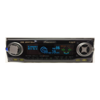
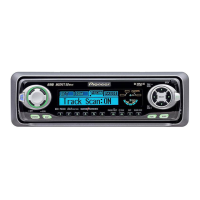
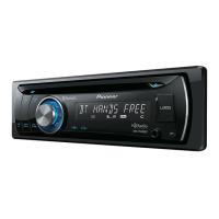
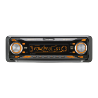
Identification and function of front panel buttons and controls on the head unit and remote.
Wiring diagrams showing connections for power, speakers, and optional components.
Procedures to confirm product quality and normal operation after repairs.
Diagrams showing the physical placement of printed circuit boards within the unit.
Tools and procedures for cleaning optical pickup lenses before shipping.
Step-by-step troubleshooting guide for power-on operation and source selection.
List of error messages, their codes, classes, and potential causes.
Details the function of each pin for various connectors on the unit.
Overview of different test modes and key allocations for the CD mechanism.
Procedure to enter and navigate the display test mode for checking screen functions.
Detailed flowchart and key operations for testing CD mechanism functions.
Cautions and procedures for adjusting the CD mechanism, including test mode entry.
Procedure to check grating angle after replacing the pickup unit for proper tracking.
How to confirm PCL output signal for operational mode checks.
Exploded view and parts list for the product packaging components.
Exploded view and parts list for external components of the unit.
Exploded view and parts list for additional external components.
Exploded view and parts list for the drive unit assembly, including lubrication points.
Exploded view and parts list for the CD mechanism module.
High-level wiring diagram showing main unit connections and signal flow.
Schematic diagram for the keyboard unit, showing button connections and control signals.
Schematic diagram for the CD mechanism module, detailing motor drivers and switch logic.
Oscilloscope waveforms for CD core unit signals during various operations.
PCB layout for the tuner amplifier unit, showing component placement and connector assignments.
PCB layout for the keyboard unit, showing component placement for buttons and controls.
PCB layout for the CD core unit, showing component placement and signal lines.
PCB layout for the switch unit, indicating switch positions.
List of integrated circuits used in the unit with their part numbers.
List of transistors used in the unit with their part numbers.
List of diodes used in the unit with their part numbers.
List of resistors used in the unit with their part numbers.
List of capacitors used in the unit with their part numbers.
| Model | DEH-P6050UB |
|---|---|
| DIN Size | 1 DIN |
| Channels | 4 |
| Max Power Output | 50 W x 4 |
| RMS Power Output | 22 W x 4 |
| Detachable Face | Yes |
| Built-in Display | Yes |
| CD Playback | Yes |
| CD-R/RW Playback | Yes |
| MP3 Playback | Yes |
| WMA Playback | Yes |
| AAC Playback | Yes |
| WAV Playback | Yes |
| ID3 Tag Display | Yes |
| AM/FM Tuner | Yes |
| FM Presets | 18 |
| AM Presets | 6 |
| USB Port | Yes |
| AUX Input | Yes |
| iPod Connection | Yes |
| Bluetooth | No |
| HD Radio | No |
| Sub Preamp Output | Yes |
| RDS | Yes |
| High-Pass Filter | Yes |
| Low-Pass Filter | Yes |
| Subwoofer Output | Yes |
| Remote Control | Yes |
| Wireless Remote | Yes |
| CEA-2006 Compliant | Yes |
| USB Compatibility | USB 2.0 |
| Satellite Radio Ready | Yes |
| RCA Preamp Outputs | 3 pairs |
| Steering Wheel Control | Yes (requires adapter) |
| Dimensions (W x H x D) | 178 x 50 x 160 mm |