EasyManua.ls Logo

Pioneer DEH P6800MP Service Manual

Pioneer DEH P6800MP
80 pages
To Next Page IconTo Next Page
Page #1 background imageLoading...
Page #1 background image
ORDER NO.
PIONEER CORPORATION 4-1, Meguro 1-chome, Meguro-ku, Tokyo 153-8654, Japan
PIONEER ELECTRONICS (USA) INC. P.O. Box 1760, Long Beach, CA 90801-1760, U.S.A.
PIONEER EUROPE NV Haven 1087, Keetberglaan 1, 9120 Melsele, Belgium
PIONEER ELECTRONICS ASIACENTRE PTE. LTD. 253 Alexandra Road, #04-01, Singapore 159936
PIONEER CORPORATION 2005
DEH-P680MP/XN/UC
CRT3569
MULTI-CD CONTROL HIGH POWER CD/MP3/WMA/AAC PLAYER WITH FM/AM TUNER
DEH-P680MP
/XN/UC
DEH-P6800MP
/XN/UC
DEH-P6850MP
/XN/ES
This service manual should be used together with the following manual(s):
Model No. Order No. Mech.Module Remarks
CX-3164 CRT3583 S10.5COMP1 CD Mech. Module:Circuit Description, Mech. Description, Disassembly
For details, refer to "Important Check Points for Good Servicing".
K-ZZA.NOV. 2005 Printed in Japan
w
w
w
.
x
i
a
o
y
u
1
6
3
.
c
o
m
Q
Q
3
7
6
3
1
5
1
5
0
9
9
2
8
9
4
2
9
8
T
E
L
1
3
9
4
2
2
9
6
5
1
3
9
9
2
8
9
4
2
9
8
0
5
1
5
1
3
6
7
3
Q
Q
TEL 13942296513 QQ 376315150 892498299
http://www.xiaoyu163.com

Other manuals for Pioneer DEH P6800MP

Question and Answer IconNeed help?

Do you have a question about the Pioneer DEH P6800MP and is the answer not in the manual?

Pioneer DEH P6800MP Specifications

General IconGeneral
Power Output50 W x 4
RMS Power Output22 W x 4
CD PlaybackYes
MP3 PlaybackYes
WMA PlaybackYes
TunerAM/FM
BluetoothNo
DIN SizeSingle DIN
Detachable FaceYes
ID3 TagYes
Preset Stations24
CD-R PlaybackYes
CD-RW PlaybackYes
AUX InputYes
Remote ControlYes
High-Pass FilterYes
Low-Pass FilterYes
Subwoofer OutputYes
USB InputNo
iPod CompatibilityNo
Satellite Radio ReadyYes
HD Radio ReadyNo
Preamp Outputs3 (Front, Rear, Subwoofer)
Preamp Voltage4V

Summary

SAFETY INFORMATION

Important Check Points for Good Servicing

Product Safety Procedures

Ensures safety during repairs by conforming to regulations and using specified parts.

Exploded Views and Parts List

Exterior Views and Parts

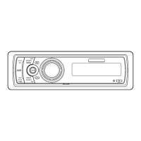
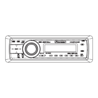
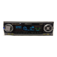
Detailed illustration of the product's exterior components and their part numbers.

CD Mechanism Module

Exploded view and parts list for the CD mechanism module.

Block and Schematic Diagrams

Block Diagram Overview

Visual representation of the system's main functional blocks and their interconnections.

Keyboard Unit Schematics

Detailed circuit diagrams and pin functions for the keyboard unit.

CD Mechanism Module Schematics

Circuit diagrams for the CD mechanism module, including motor drivers and switches.

CD Core Unit Schematics

Circuit diagrams for the CD Core Unit, detailing its ICs and connections.

PCB Connection Diagrams

Tuner Amp Unit PCB Layout

Shows component placement and connector locations on the Tuner Amp Unit PCB.

CD Core Unit PCB Layout

Component layout and connections for the CD Core Unit (S10.5COMP1).

Electrical Parts List

Integrated Circuits (ICs)

List of integrated circuits with part numbers and specifications.

Adjustment Procedures

CD Adjustment Cautions

Important precautions and guidelines for performing CD adjustments safely.

Grating Check Procedure

Steps to check the grating angle after replacing the pickup unit using an oscilloscope.

Error Mode and Codes

Error Code List and Descriptions

Table detailing error codes, their classes, displayed errors, and potential causes.

Clock Frequency Check

Procedure to check the clock signal frequency and replace the X'tal if necessary.

System Block Diagram

Connection Diagrams

Related product manuals