Do you have a question about the Pioneer DEH-P680MP and is the answer not in the manual?
Guidelines for safe servicing procedures, including regulations and handling precautions for unit components.
Ensuring product safety by adhering to regulations, using specified parts, and following proper repair methods.
Maintaining original product performance through proper adjustments and confirmations as per manual.
Using specified lubricants and adhesives, and ensuring correct application amount.
Proper cleaning of parts like optical pickups and lenses to restore performance.
Setting shipping mode or installing shipping screws before shipment to prevent transit damage.
List of parts included in the packing section for various models.
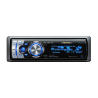
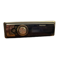
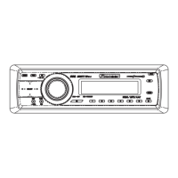
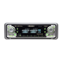
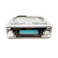
Details and diagrams related to the external appearance and components of the unit.
Detailed list of parts for the exterior section, including their part numbers.
Diagrams and parts list for the CD mechanism module.
Parts list specific to the CD mechanism module.
Overall system block diagram illustrating functional units and their interconnections.
A guide page illustrating the Tuner Amplifier Unit schematic.
Schematic diagram for the Keyboard Unit, detailing component connections and functions.
Schematic diagram for the CD Core Unit, detailing signal lines and component connections.
Tuner Amp Unit PCB connection diagram and layout.
PCB connection diagram for wired remote control and RCA interface.
CD Core Unit PCB connection diagram and layout.
Keyboard Unit PCB connection diagram and layout.
List of miscellaneous electrical components, including ICs, transistors, diodes, and resistors.
Procedure for adjusting the CD mechanism, including cautions and test mode operations.
Procedure to check grating angle after replacing the pickup unit, including symptoms and hints.
List of error codes, their displayed errors, and potential causes for troubleshooting.
Procedure to check clock signal frequency and replace X'tal if out of range.
Guide for diagnosing issues and disassembling unit components like the case, CD mechanism, and grille.
Steps for removing the Tuner Amp Unit, handling the mechanism, and removing CD Core/Pickup units.
Detailed description of connector pin functions and IC pinouts for system components.
Description of buttons and functions on the main unit's control panel.
Explanation of buttons and controls on the remote commander.
Diagram showing connections for rear speaker leads to the subwoofer.
Wiring diagram for connecting components without using the optional amplifier.
List of jigs used for maintenance and adjustment, including test discs and L.P.F.
List of greases and their application remarks for CD mechanism module.
| Brand | Pioneer |
|---|---|
| Model | DEH-P680MP |
| Category | Car Receiver |
| Language | English |