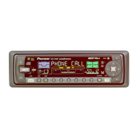
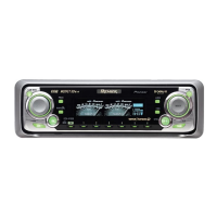
Do you have a question about the Pioneer DEH-P6000 and is the answer not in the manual?
Lists all parts included in the product packaging for various models.
Details all external components and their part numbers for different models.
Provides a comprehensive list of parts for the CD mechanism module.
Illustrates the functional blocks of the Tuner Amp Unit.
Shows comprehensive connection layouts for different models.
Details the schematic and block diagram for the FM/AM tuner unit.
Presents the block and schematic diagram for the keyboard unit.
Provides the block and schematic diagram for the CD mechanism module.
Shows the component layout and connections for the Tuner Amp Unit PCB.
Illustrates the component layout and connections for the FM/AM Tuner Unit PCB.
Depicts the component layout and connections for the Keyboard Unit PCB.
Shows the component layout and connections for the CD Mechanism Module PCB.
Step-by-step flow chart for performing CD mechanism adjustments.
Procedure to check grating angle after replacing the pickup unit.
Details pin functions for various ICs used in the unit.
Shows segment and common pin layouts for the display.
Step-by-step instructions for disassembling unit components.
Explains test mode procedures, error codes, and status displays.
Guides on basic operations for the head unit and remote controller.
Provides detailed technical specifications for the unit.
| CD Playback | Yes |
|---|---|
| MP3 Playback | Yes |
| USB Input | No |
| Bluetooth | No |
| Preamp Outputs | 3 (Front, Rear, Subwoofer) |
| DIN Size | Single DIN |
| Detachable Face | Yes |
| Preamp Voltage | 4V |
| ID3 Tag Display | Yes |
| High-Pass Filter | Yes |
| Low-Pass Filter | Yes |
| Subwoofer Output | Yes |
| Channels | 4 |
| CD Player | Yes |
| RMS Power Output | 22W x 4 Channels |
| Tuner | FM/AM |
| Equalizer | Yes |
| Power Output | 50W x 4 Channels |