EasyManua.ls Logo

Pioneer DEH-P600 Service Manual

Pioneer DEH-P600
102 pages
To Next Page IconTo Next Page
Page #1 background imageLoading...
Page #1 background image
PIONEER ELECTRONIC CORPORATION 4-1, Meguro 1-Chome, Meguro-ku, Tokyo 153-8654, Japan
PIONEER ELECTRONICS SERVICE INC. P.O.Box 1760, Long Beach, CA 90801-1760 U.S.A.
PIONEER ELECTRONIC [EUROPE] N.V. Haven 1087 Keetberglaan 1, 9120 Melsele, Belgium
PIONEER ELECTRONICS ASIACENTRE PTE.LTD. 253 Alexandra Road, #04-01, Singapore 159936
C PIONEER ELECTRONIC CORPORATION 1999
K-ZZD. FEB. 1999 Printed in Japan
ORDER NO.
CRT2374
MULTI-CD CONTROL HIGH POWER CD PLAYER WITH FM/AM TUNER
DEH-P600 UC
Service
Manual
CONTENTS
1. SAFETY INFORMATION ............................................2
2. EXPLODED VIEWS AND PARTS LIST.......................2
3. BLOCK DIAGRAM AND SCHEMATIC DIAGRAM ...14
4. PCB CONNECTION DIAGRAM ................................48
5. ELECTRICAL PARTS LIST ........................................58
6. ADJUSTMENT..........................................................71
7. GENERAL INFORMATION .......................................75
7.1 PARTS .................................................................75
7.1.1 IC................................................................75
7.1.2 DISPLAY....................................................82
7.2 DIAGNOSIS ........................................................83
7.2.1 DISASSEMBLY .........................................83
7.2.2 TEST MODE..............................................88
8. OPERATIONS AND SPECIFICATIONS.....................92
- See the separate manual CX-916(CRT2300) for the CD mechanism description, disassembly and circuit
description.
- The CD mechanism employed in this model is one of S8 series.
- This device employs an inverter as the power supply for EL. The inverter has an output voltage reach
approximately 500 volts(AC). Utmost care should be used not to suffer from a possible electric shock,
accordingly.
- When executing an operation, be aware that the in around IC651 can become quite hot to the touch.
DEH-P6000 UC
DEH-P6050 ES
DEH-P600/UC
Question and Answer IconNeed help?

Do you have a question about the Pioneer DEH-P600 and is the answer not in the manual?

Pioneer DEH-P600 Specifications

General IconGeneral
ModelDEH-P600
DIN SizeSingle DIN
TunerAM/FM
CD PlaybackYes
MP3 PlaybackYes
WMA PlaybackYes
USB PortNo
BluetoothNo
Preamp Outputs3 (Front, Rear, Subwoofer)
Preamp Voltage4V
EqualizerYes
Detachable FaceplateYes
Remote ControlYes
Subwoofer ControlYes
HD RadioNo
Frequency Response5 Hz - 20 kHz
Power Output50W x 4 Channels
RMS Power Output22W x 4 Channels
Auxiliary InputYes
iPod CompatibilityYes
EQ Bands5 Bands

Summary

SAFETY INFORMATION

EXPLODED VIEWS AND PARTS LIST

2.1 PACKING (DEH-P600/UC)

Lists parts for product packaging and unboxing.

EXTERIOR SECTION PARTS LIST

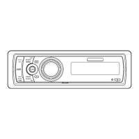
Detailed list of external parts.

CD MECHANISM MODULE SECTION PARTS LIST

Detailed list of parts for the CD mechanism module.

BLOCK DIAGRAM AND SCHEMATIC DIAGRAM

3.1 BLOCK DIAGRAM (DEH-P600/UC)

Block diagram illustrating the unit's functional blocks.

3.7 FM/AM TUNER UNIT

Schematic diagram of the FM/AM tuner unit.

3.8 KEYBOARD UNIT

Schematic diagram of the keyboard unit.

3.9 CD MECHANISM MODULE

Schematic diagram of the CD mechanism module.

PCB CONNECTION DIAGRAM

4.1 TUNER AMP UNIT

PCB connection diagram for the tuner amp unit.

4.2 FM/AM TUNER UNIT

PCB connection diagram for the FM/AM tuner unit.

4.3 KEYBOARD UNIT

PCB connection diagram for the keyboard unit.

4.4 CD MECHANISM MODULE

PCB connection diagram for the CD mechanism module.

ELECTRICAL PARTS LIST

MISCELLANEOUS COMPONENTS

List of miscellaneous electrical components.

RESISTORS

List of resistor components.

CAPACITORS

List of capacitor components.

ADJUSTMENT

6.1 CD ADJUSTMENT

Precautions and procedures for CD adjustment.

6.2 CHECKING THE GRATING AFTER CHANGING THE PICKUP UNIT

Procedure to check pickup unit grating angle.

GENERAL INFORMATION

7.1.1 IC

Pin functions for IC PE5005A.

7.2.1 DISASSEMBLY

Step-by-step instructions for disassembling the unit.

7.2.2 TEST MODE

Explanation of test mode and error messages.

OPERATIONS AND SPECIFICATIONS

8.1 OPERATIONS

Overview of head unit and remote controller operations.

Basic Operation of Built-in CD Player

Details operations for the built-in CD player.

Basic Operation of Tuner

Explains manual tuning, seek tuning, and preset tuning.

Audio Adjustment

Explains selecting equalizer curves and entering audio menu.

8.2 SPECIFICATIONS

Lists technical specifications for the unit.

Related product manuals