Do you have a question about the Pioneer DEH-P9000R and is the answer not in the manual?
Essential safety measures for technicians working on the unit, including laser handling.
Technical details on laser radiation fields and wavelength for safe handling.
Exploded view and parts list for the product's packing components.
Detailed list of parts included in the product's packaging.
List of associated documentation parts like manuals and cards.
Detailed list of parts related to the exterior of the unit.
Detailed list of parts for the CD mechanism module.
High-level functional overview of the unit's main blocks.
Detailed electrical schematic showing component connections and layout.
Block diagram and schematic for the FM/AM tuner section.
Block diagram and schematic for the keyboard unit.
Block diagram and schematic for the DSP unit.
Block diagram and schematic for the ASL unit.
Block diagram and schematic for the CD mechanism module.
Diagram showing component placement and connections on the Tuner Amp PCB.
Detailed layout of components on the Tuner Amp PCB.
Diagram showing component placement and connections on the FM/AM Tuner PCB.
Diagram showing component placement and connections on the Keyboard PCB.
Diagram showing component placement and connections on the DSP PCB.
Diagram showing component placement and connections on the ASL PCB.
Diagram showing component placement and connections on the Switch PCB.
Diagram showing component placement and connections on the Mic Jack PCB.
Diagram showing component placement and connections on the CD Mechanism Module PCB.
General list of electrical components not specific to a unit.
Detailed list of electrical parts for the Tuner Amp Unit.
List of resistors with their part numbers and circuit symbols.
List of capacitors with their part numbers and circuit symbols.
Detailed list of electrical parts for the FM/AM Tuner Unit.
Detailed list of electrical parts for the Keyboard Unit.
Detailed list of electrical parts for the DSP Unit.
Detailed list of electrical parts for the ASL Unit.
Detailed list of electrical parts for the Photo Unit.
Summary of general electrical parts.
Procedures for adjusting CD playback functions and parameters.
Visual flowchart guiding the CD adjustment process and mode selections.
Procedure to check grating angle after replacing the pickup unit.
Visual examples of grating waveforms at different angles for analysis.
Information and methods for diagnosing unit issues.
How to enter and use the diagnostic test mode for the unit.
Explanation of error codes and their potential causes for troubleshooting.
List of operational statuses displayed during the setup process.
Examples of unit displays during setup and operation, including error scenarios.
How protection errors are indicated and displayed on the unit.
Step-by-step guide for disassembling the unit's main modules.
Procedures for removing the Tuner Amp and DSP units.
Steps for removing the upper frame and carriage mechanism.
Procedure for removing the clamp arm assembly.
Steps for removing guide arm, LO arm, and control unit.
Procedures for removing motors and the pickup unit.
Detailed pinouts and functions of integrated circuits.
Specific pin functions for the PD5482A integrated circuit.
Specific pin functions for the PD5504A integrated circuit.
Specific pin functions for the PD5471A integrated circuit.
Specific pin functions for the PD8051A integrated circuit.
Specific pin functions for the AK7714 integrated circuit.
Specific pin functions for the UPD63710GC integrated circuit.
Specific pin functions for the PE5011C integrated circuit.
Specific pin functions for the BA5985FM integrated circuit.
Specific pin functions for the PD0236AM integrated circuit.
Technical specifications for the unit's various functions and components.
Diagram illustrating external connections for audio, power, and antenna.
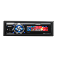
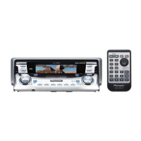
Guide to operating the unit's main functions and controls.
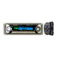
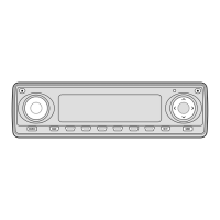
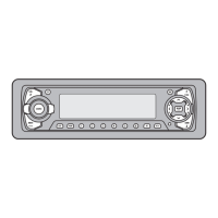
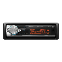
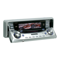
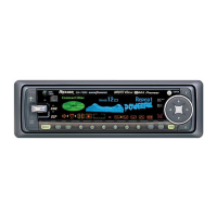
Identification and layout of all buttons and indicators on the front panel.
Step-by-step guide for selecting sources and listening to audio.
Explanation of tuner operations like manual tuning, seek tuning, and preset tuning.
Guide to operating the CD player functions like track search and eject.
How to navigate and view information on the CD player display.
Instructions for operating with multiple CD players, including disc selection.
| Category | Car Receiver |
|---|---|
| DIN Size | 1 DIN |
| Tuner | AM/FM |
| CD Playback | Yes |
| MP3 Playback | No |
| WMA Playback | No |
| Display Type | LCD |
| Preamp Outputs | Yes |
| Equalizer | Yes |
| Bluetooth | No |
| Detachable Face | Yes |
| Preamp Outputs Channels | 3 |
| Equalizer Bands | 5 |
| Built-in DSP | No |
| Equalizer Type | Graphic |
| Detachable Faceplate | Yes |
| Remote Control | Yes |
| RMS Power Output | 22 Watts x 4 |
| Power Output | 50 Watts x 4 |