EasyManua.ls Logo

Pioneer DEH-P920R User Manual

Pioneer DEH-P920R
111 pages
To Next Page IconTo Next Page
Page #1 background imageLoading...
Page #1 background image
PIONEER CORPORATION 4-1, Meguro 1-Chome, Meguro-ku, Tokyo 153-8654, Japan
PIONEER ELECTRONICS SERVICE INC. P.O.Box 1760, Long Beach, CA 90801-1760 U.S.A.
PIONEER EUROPE N.V. Haven 1087 Keetberglaan 1, 9120 Melsele, Belgium
PIONEER ELECTRONICS ASIACENTRE PTE.LTD. 253 Alexandra Road, #04-01, Singapore 159936
C PIONEER CORPORATION 2000
K-ZZD. FEB. 2000 Printed in Japan
ORDER NO.
CRT2486
MULTI-CD/DAB CONTROL DSP HIGH POWER CD PLAYER WITH RDS TUNER
DEH-P920R UC
Service
Manual
- This service manual should be used together with the following manual(s):
Model No. Order No. Mech. Module Remarks
CX-916 CRT2300 S8 CD Mech. Module:Circuit Description, Mech.Description, Disassembly
CONTENTS
1. SAFETY INFORMATION ............................................2
2. EXPLODED VIEWS AND PARTS LIST.......................3
3. BLOCK DIAGRAM AND SCHEMATIC DIAGRAM ...14
4. PCB CONNECTION DIAGRAM ................................46
5. ELECTRICAL PARTS LIST ........................................58
6. ADJUSTMENT..........................................................74
7. GENERAL INFORMATION .......................................78
7.1 DIAGNOSIS ........................................................78
7.1.1 TEST MODE..............................................78
7.1.2 DISASSEMBLY .........................................82
7.2 IC ........................................................................87
8. OPERATIONS AND SPECIFICATIONS...................101
MULTI-CD/MD/DAB CONTROL HIGH POWER CD PLAYER WITH RDS TUNER
DEH-P9200R UC
DEH-P9250 ES
MULTI-CD CONTROL DSP HIGH POWER CD PLAYER WITH FM/AM TUNER
DEH-P920R/UC
Question and Answer IconNeed help?

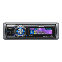
Do you have a question about the Pioneer DEH-P920R and is the answer not in the manual?

Pioneer DEH-P920R Specifications

General IconGeneral
BrandPioneer
ModelDEH-P920R
CategoryCar Receiver
LanguageEnglish

Summary

SAFETY INFORMATION

Safety Precautions and Warnings

Details safety precautions, cautions, and health warnings for service technicians.

EXPLODED VIEWS AND PARTS LIST

Packing Section Parts List

Lists parts and their order numbers for product packaging and contents.

Exterior Section Parts List

Lists external components and their part numbers for various models.

CD Mechanism Module Parts List

Lists all parts and their numbers for the CD mechanism module.

BLOCK DIAGRAM AND SCHEMATIC DIAGRAM

System Unit Block Diagrams

Provides block diagrams for Tuner, Control, CD Mechanism, DSP, ASL, and Keyboard units.

Connection Diagrams

Shows overall connection diagrams for DEH-P920R/UC, DEH-P9200R/UC, and DEH-P9250/ES.

Waveforms

Signal Waveform Examples

Displays oscilloscope waveforms for various test modes and operational conditions.

PCB CONNECTION DIAGRAMS

Tuner Amp Unit PCB Layout

Shows the component layout and connections for the Tuner Amp Unit PCB.

FM/AM Tuner Unit PCB Layout

Illustrates the PCB layout and component placement for the FM/AM Tuner Unit.

Keyboard Unit PCB Layout

Details the PCB layout and component placement for the Keyboard Unit.

DSP Unit PCB Layout

Shows the PCB layout and component placement for the DSP Unit.

ASL Unit PCB Layout

Illustrates the PCB layout and component placement for the ASL Unit.

Switch & Mic Jack PCB Layouts

Displays PCB layouts for the Switch PCB and Mic Jack PCB.

CD Mechanism Module PCB Layout

Shows the PCB layout and component placement for the CD Mechanism Module.

ELECTRICAL PARTS LIST

Miscellaneous Components

Lists miscellaneous electronic components like ICs, transistors, diodes, and resistors.

ADJUSTMENT

CD Adjustment Procedures

Details procedures for adjusting CD mechanism parameters like focus and tracking.

Checking Grating After Pickup Unit Change

Describes how to check and adjust the pickup unit’s grating angle for optimal performance.

GENERAL INFORMATION

Diagnosis and Test Modes

Explains error messages, codes, test modes, and diagnostic procedures for troubleshooting.

DISASSEMBLY PROCEDURES

Component Removal Steps

Provides step-by-step instructions for disassembling the unit and its modules.

IC PIN FUNCTIONS REFERENCE

Pin Assignments for Key ICs

Lists pin functions for key ICs used in the device for reference.

OPERATIONS AND SPECIFICATIONS

Unit Operations Overview

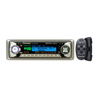
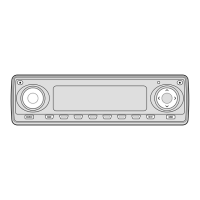
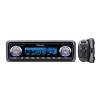
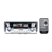
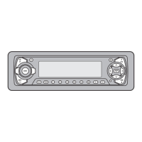
Explains basic operations of the head unit and remote controller functions.

Technical Specifications

Lists detailed technical specifications for the unit's performance and features.

Related product manuals