EasyManua.ls Logo

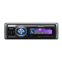
Pioneer deh-p980bt User Manual

Pioneer deh-p980bt
148 pages
To Next Page IconTo Next Page
Page #1 background imageLoading...
Page #1 background image
ORDER NO.
PIONEER CORPORATION 4-1, Meguro 1-chome, Meguro-ku, Tokyo 153-8654, Japan
PIONEER ELECTRONICS (USA) INC. P.O. Box 1760, Long Beach, CA 90801-1760, U.S.A.
PIONEER EUROPE NV Haven 1087, Keetberglaan 1, 9120 Melsele, Belgium
PIONEER ELECTRONICS ASIACENTRE PTE. LTD. 253 Alexandra Road, #04-01, Singapore 159936
PIONEER CORPORATION 2006
DEH-P980BT/XN/UC
CRT3687
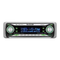
MULTI-CD CONTROL DSP HIGH POWER CD/MP3/WMA/AAC PLAYER
WITH BLUETOOTH WIRELESS TECHNOLOGY AND FM/AM TUNER
DEH-P980BT
/XN/UC
DEH-P9800BT
/XN/UC
DEH-P9850BT
/XN/ES
This service manual should be used together with the following manual(s):
Model No. Order No. Mech.Module Remarks
CX-3164 CRT3583 S10.5COMP1 CD Mech. Module : Circuit Descriptions, Mech. Descriptions, Disassembly
For details, refer to "Important Check Points for Good Servicing".
K-ZZD.MAY 2006 Printed in Japan
w
w
w
.
x
i
a
o
y
u
1
6
3
.
c
o
m
Q
Q
3
7
6
3
1
5
1
5
0
9
9
2
8
9
4
2
9
8
T
E
L
1
3
9
4
2
2
9
6
5
1
3
9
9
2
8
9
4
2
9
8
0
5
1
5
1
3
6
7
3
Q
Q
TEL 13942296513 QQ 376315150 892498299
http://www.xiaoyu163.com
Question and Answer IconNeed help?

Do you have a question about the Pioneer deh-p980bt and is the answer not in the manual?

Pioneer deh-p980bt Specifications

General IconGeneral
BrandPioneer
Modeldeh-p980bt
CategoryCar Stereo System
LanguageEnglish

Summary

SAFETY INFORMATION

CAUTION

General warnings for technicians regarding product safety and proper repair procedures.

WARNING

Health and safety warning regarding chemicals in the product (California Proposition 65).

Laser Diode Safety Precautions

Specific precautions for handling laser diode emission during service.

[Important Check Points for Good Servicing]

Product Safety Guidelines

Guidelines for safe product handling, repair, and servicing environment.

1. SPECIFICATIONS

2. EXPLODED VIEWS AND PARTS LIST

2.4 CD MECHANISM MODULE

3. BLOCK DIAGRAM AND SCHEMATIC DIAGRAM

3.6 BLUETOOTH & ANTENNA UNITS

4. PCB CONNECTION DIAGRAMS

4.1 TUNER AMP UNIT PCB

PCB connection diagram for the Tuner Amplifier Unit, showing component layout and connections.

4.2 KEYBOARD UNIT PCB Diagram

4.3 CD CORE UNIT PCB Diagram

4.4 BLUETOOTH UNIT PCB Diagram

4.5 ANTENNA UNIT PCB Diagram

4.6 SWITCH UNIT PCB Diagram

6. ADJUSTMENT PROCEDURES

6.2 CD ADJUSTMENT

CD Adjustment Cautions

Important precautions and warnings related to CD adjustment procedures.

CD Test Mode Entry and Exit

Instructions for entering and exiting the test mode for CD mechanism adjustment.

7. OPERATIONAL FLOW CHART

6.3 GRATING CHECK AFTER PICKUP CHANGE

Grating Check Method and Procedure

Required equipment and step-by-step instructions for checking the grating angle.

6.4 ERROR MODE

Error Code Information

Explanation of error modes, their display on unit, and code list with causes.

6.5 SYSTEM MICROCOMPUTER TEST

6.6 REVOLUTION NUMBER DETECTION CHECK

6.7 E.VOL IC OSCILLATING FREQUENCY ADJUSTMENT

Frequency Adjustment Procedure

Steps for adjusting the E.VOL IC oscillating frequency using a frequency counter.

6.8 BLUETOOTH TEST MODE

Bluetooth Test Mode Specifications

Cautions and Function Outline

Important notes and key functions for Bluetooth action checks with mobile phones.

4. START-UP TEST MODE

Operation Method for Test Modes

Step-by-step guide to starting and navigating test modes for Bluetooth and Flash memory.

Bluetooth Test Mode with Spectrum Analyzer

Analyzer Setup and Cautions

Requirements and precautions for testing Bluetooth output level with a 2.4 GHz spectrum analyzer.

4. Start-up Test Mode Operation

Local TX NM Mode Operation

Detailed steps for starting and operating the Local TX NM test mode and frequency selection.

Mechanism Unit Disassembly

CD Unit and Pickup Removal

Connection Diagrams

1. CIRCUIT DESCRIPTIONS

CD LSI Block Diagram

Block diagram of the main CD LSI, detailing its functional blocks.

1.1 PREAMPLIFIER BLOCK

1.1.1 APC Circuit Explanation

Explanation of the Automatic Power Control circuit for laser diode current stabilization.

1.1.2 RF and RFAGC Amplifiers

1.1.3-1.1.5 Servo Amplifier Circuits

1.1.6-1.1.7 Signal Processing Circuits

1.2 SERVO BLOCK

1.2.1 Focus Servo System

Explanation of the focus servo system, including lens movement and conditions for focus closure.

1.2.2 Tracking Servo System

1.2.3 Carriage Servo System

1.2.4 Spindle Servo System

1.3 AUTOMATIC ADJUSTMENT FUNCTION

TE, FE, RF Offset Auto-Adjustment

Procedure for adjusting TE, FE, and RF amplifier offsets to target values.

Tracking Balance (T.BAL) Auto-Adjustment

Procedure for equalizing E-ch/F-ch output difference for symmetrical TE waveform.

FE Bias Auto-Adjustment

Procedure to maximize RFO level by optimizing focus point and detecting RF waveform relation.

Automatic Adjustment Procedures

Focus and Tracking AGC

Procedure for automatically adjusting focus and tracking servo loop gains.

RF Level Auto-Adjustment (RFAGC)

Procedure to adjust RF level dispersion for stable signal transmission.

Coefficient Display of Adjustment Results

1.4 POWER SUPPLY AND LOADING BLOCK

2. MECHANISM DESCRIPTIONS

Loading Actions

Steps involved in loading discs (8cm/12cm) and the role of switches and motors.

Mechanism Actions

3. DISASSEMBLY

Pickup Unit Removal

Load Carriage Motor Assy Removal

Clamp Arm and Spindle Motor Assy Removal

Related product manuals