EasyManua.ls Logo

Pioneer deh-p40mp User Manual

Pioneer deh-p40mp
70 pages
To Next Page IconTo Next Page
Page #1 background imageLoading...
Page #1 background image
ORDER NO.
PIONEER CORPORATION 4-1, Meguro 1-chome, Meguro-ku, Tokyo 153-8654, Japan
PIONEER ELECTRONICS (USA) INC. P.O. Box 1760, Long Beach, CA 90801-1760, U.S.A.
PIONEER EUROPE NV Haven 1087, Keetberglaan 1, 9120 Melsele, Belgium
PIONEER ELECTRONICS ASIACENTRE PTE. LTD. 253 Alexandra Road, #04-01, Singapore 159936
PIONEER CORPORATION 2006
DEH-P40MP/XU/EW5
CRT3834
CD RDS RECEIVER
DEH-P40MP
/XU/EW5
This service manual should be used together with the following manual(s):
Model No. Order No. Mech.Module Remarks
CX-3195 CRT3815 S10.5COMP2 CD Mech. Module : Circuit Descriptions, Mech. Descriptions, Disassembly
For details, refer to "Important Check Points for Good Servicing".
K-ZZA. NOV. 2006 Printed in Japan

Other manuals for Pioneer deh-p40mp

Question and Answer IconNeed help?

Do you have a question about the Pioneer deh-p40mp and is the answer not in the manual?

Pioneer deh-p40mp Specifications

General IconGeneral
BrandPioneer
Modeldeh-p40mp
CategoryCar Stereo System
LanguageEnglish

Summary

SAFETY INFORMATION

Service Technician Safety

Precautions for qualified service personnel handling the unit.

Laser Diode Safety Precautions

Warnings and precautions regarding the laser diode emission and handling.

[Important Check Points for Good Servicing]

Servicing Precautions and Guidelines

Product safety, adjustments, lubricants, cleaning, and shipping procedures.

1. SPECIFICATIONS

System Specifications

Covers general, audio, and tuner details like power, dimensions, and frequency ranges.

2. EXPLODED VIEWS AND PARTS LIST

Parts Identification

Exploded views and lists for packing, exterior, and mechanism components.

3. BLOCK DIAGRAM AND SCHEMATIC DIAGRAM

System Diagrams

Block, connection, and unit-specific diagrams for system architecture.

6. ADJUSTMENT

CD Adjustment and Error Modes

CD adjustment, grating check, error codes, and test programs.

7. GENERAL INFORMATION

Diagnosis, Disassembly, and Connectors

Diagnosis, disassembly steps, and connector functions.

Component Pin Functions and Unit Details

Pinouts for ICs, tuner unit, and display.

8. OPERATIONS

Unit and Remote Control Operations

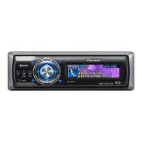
Explains head unit and remote control functions.

Related product manuals