Do you have a question about the Pioneer DEH-P7000UB and is the answer not in the manual?
Precautions for technicians servicing the unit, including laser safety.
Guidelines for ensuring product safety during repairs, including parts and modifications.
Procedures for optimum adjustments and performance confirmation.
Guidance on using specified lubricants, glues, and replacement parts.
Steps for cleaning specific parts to restore performance.
Instructions for setting shipping mode or installing screws before shipment.
General precautions for safe and proper servicing procedures.
Guidance on using lead-free solder and proper soldering techniques.
Detailed technical specifications for the unit, including power, dimensions, and audio capabilities.
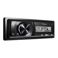
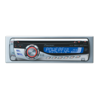
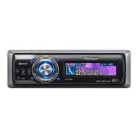
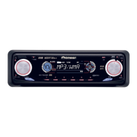
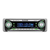
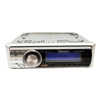
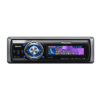
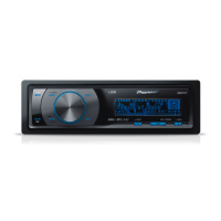
Description of the functions of buttons and controls on the head unit.
Procedures to confirm product quality and customer complaint resolution after servicing.
Identification and location of the main Printed Circuit Boards within the unit.
Block diagram illustrating the Tuner Amp Unit components and connections.
Step-by-step procedure for removing the keyboard unit from the device.
Instructions for detaching the holder, panel, and case assembly.
Procedure for safely removing the CD mechanism module.
Steps for removing the panel assembly, including screws and arrows.
Procedures and cautions for adjusting the CD mechanism module, including test mode.
Information regarding PU unit grating angle adjustment and its limitations.
Objective of checking the grating angle within acceptable range after PU unit replacement.
Signs indicating grating misalignment, affecting tracking and search operations.
Required equipment, points, disc, and mode for checking the grating.
Step-by-step guide to monitor LPF outputs and check phase difference for grating alignment.
Explanation of waveform "wobble" due to disc eccentricity and clamping center misalignment.
Suggestion to reload the disc to potentially decrease waveform "wobble".
Procedure to confirm PCL output signal from IC601, including frequency and terminal.
Exploded view and parts list for the packing section of the unit.
Overall connection diagram illustrating the system's interconnected components.
Oscilloscope waveforms for CD Core Unit operations like loading, setup, and play.
Waveform display for focus search operation, showing signal behavior.
Waveform display for track open operation, illustrating signal characteristics.
Waveform display for 1 track jump operation, showing signal response.
Waveform display for USB/iPod connection status with ACC OFF.
Waveform display showing the iPod authentication process.
Zoomed waveform of iPod authentication, focusing on the first 2 seconds.
PCB connection diagram for the Tuner Amp Unit, showing component layout and connectors.
PCB layout for the Keyboard Unit, indicating component placement and connections.
PCB layout for the Keyboard Unit, SIDE B, showing component placement and connections.
PCB layout for the CD Core Unit, showing component placement and connections.
PCB layout for the CD Core Unit, SIDE B, showing component placement and connections.
PCB layout for the Switch Unit, indicating switches and connector CN871.
List of chip resistors used in the unit, with circuit symbols, numbers, and part numbers.
List of chip capacitors, excluding CQS types, with circuit symbols and part numbers.
List of miscellaneous components like ICs, diodes, transistors, and LEDs with their part numbers.
| MP3 playback | Yes |
|---|---|
| Audio formats supported | AAC, MP3, WAV, WMA |
| Supported radio bands | AM, FM |
| Product color | Black |
| Audio output channels | 4.0 channels |
| Equalizer bands quantity | 7 |
| Maximum power per channel | 50 W |
| Illumination color | Blue |
| File type | MP3, WMA, WAV, AAC |
| I/O ports | 3x RCA 1x USB |