EasyManua.ls Logo

Pioneer DEH-X16UB/XNUC User Manual

Pioneer DEH-X16UB/XNUC
63 pages
To Next Page IconTo Next Page
Page #1 background imageLoading...
Page #1 background image
ORDER NO.
PIONEER CORPORATION 1-1, Shin-ogura, Saiwai-ku, Kawasaki-shi, Kanagawa 212-0031, Japan
PIONEER ELECTRONICS (USA) INC. P.O. Box 1760, Long Beach, CA 90801-1760, U.S.A.
PIONEER EUROPE NV Haven 1087, Keetberglaan 1, 9120 Melsele, Belgium
PIONEER ELECTRONICS ASIACENTRE PTE. LTD. 253 Alexandra Road, #04-01, Singapore 159936
PIONEER CORPORATION 2013
DEH-X16UB/XNUC
CRT5366
CD RDS RECEIVER
DEH-X16UB
/XNUC
DEH-X1650UB/XNCS
DEH-X1650UB/XNGS
DEH-X1650UBG/XNGS
DEH-X1650UB/XNGS1
DEH-X1690UB/XNID
This service manual should be used together with the following manual(s):
Model No. Order No. Mech. Module Remarks
CX-3287
CRT4759 S11.6STD CD Mech. Module : Circuit Descriptions, Mech. Descriptions, Disassembly
K-ZZZ JULY 2013 Printed in Japan
Question and Answer IconNeed help?

Do you have a question about the Pioneer DEH-X16UB/XNUC and is the answer not in the manual?

Pioneer DEH-X16UB/XNUC Specifications

General IconGeneral
BrandPioneer
ModelDEH-X16UB/XNUC
CategoryCar Receiver
LanguageEnglish

Summary

Service Manual Overview and Product Identification

Product Model Information

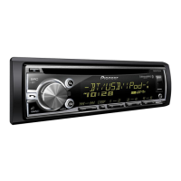
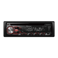
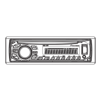
Lists the Pioneer CD RDS Receiver models covered by this manual.

Safety and Precautions

General Safety and Technician Warnings

Emphasizes technician qualifications, chemical warnings, and laser safety precautions.

Battery and Laser Diode Cautions

Details battery replacement risks and specific laser diode handling guidelines.

Service Precautions and Soldering

Covers general service procedures, handling ICs, and notes on lead-free soldering.

Product Specifications

Model Specifications (DEH-X16 Series)

Details general, audio, CD, USB, tuner, CEA2006 specs, and disc formats for various models.

Service Procedures and Diagnosis

Basic Service Items and PCB Layouts

Covers post-servicing checks, PCB locations, jigs, and cleaning procedures.

Diagnosis and Error Codes

Explains operational flowcharts, common errors, and lists CD error codes with causes.

Troubleshooting Common Issues

Provides solutions for amplifier, CD player, and USB device errors.

System Diagrams and Schematics

Block Diagrams

Illustrates functional blocks of Tuner Amp, CD Core, and USB regulator units.

Tuner Amp Unit Schematics

Details the circuitry and connections of the Tuner Amp Unit.

Keyboard and CD Core Unit Schematics

Provides schematics for Keyboard and CD Core Units, including ICs and connections.

Service Modes and Adjustments

Display Test Modes

Explains procedures for Display Test Mode 1 and 2 for checking LCD and system version.

Software Update and CD Test Mode

Details USB software upgrading and CD Test Mode operations for adjustments.

CD Adjustment and Grating Check

Covers CD adjustment cautions, test mode procedures, and checking the grating angle.

Disassembly and Parts

Unit Disassembly Procedures

Step-by-step guides for disassembling the panel, CD mechanism, and tuner amp units.

PU Unit Removal and Handling

Details PU unit removal, mecha unit handling, and grating waveform examples.

Exterior and Mechanism Parts

Provides exploded views and parts lists for exterior components and the CD mechanism module.

Waveforms and PCB Layouts

CD Core Unit Waveforms

Shows various waveforms related to CD operations for diagnosis.

PCB Connection Diagrams

Illustrates PCB layouts and connection diagrams for Tuner Amp, Keyboard, and CD Core Units.

Electrical Parts List

Component Part Numbers (ICs, Resistors, Capacitors)

Lists part numbers for ICs, transistors, resistors, inductors, capacitors, LEDs, and miscellaneous components.

Related product manuals