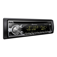
Do you have a question about the Pioneer DEH-X1810UB/XNUC and is the answer not in the manual?
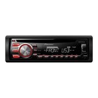
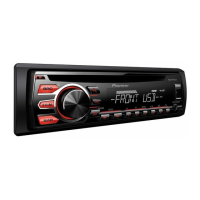
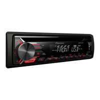
| Brand | Pioneer |
|---|---|
| Model | DEH-X1810UB/XNUC |
| Category | Car Receiver |
| Language | English |
Guidelines for safe handling and adjustments during servicing.
Cautions related to laser diode emission and exposure during testing.
Caution regarding potential explosion risk from incorrect battery replacement.
Conforming to regulations and following safety instructions during servicing.
Important considerations before and during unit disassembly and assembly.
Careful handling of ICs and parts to prevent damage from electrostatic discharge.
Notes on required adjustments after replacing specific parts.
Recommendations for using lead-free solder and soldering irons.
Key electrical and operational specifications for the unit.
Supported disc types and content formats for playback.
Confirms that customer complaints are resolved and operations are normal.
Identification and location of main PCB units within the chassis.
List of special jigs and tools required for specific service tasks.
Instructions for cleaning specific parts like the CD pickup lenses.
Overall functional block diagram of the system architecture.
Block diagram illustrating power distribution and voltage regulation.
Step-by-step process for diagnosing unit operation and potential faults.
Table of error codes, classification, and their detailed causes.
Details the function of each connector pin on the unit's rear panel.
Procedure for checking fuses to diagnose power-related issues.
Visual representation of critical signal waveforms for diagnostic purposes.
Mode for testing LCD and Grille illumination states.
Mode for checking system microcomputer version and display status.
Procedure for upgrading the MCU software using a USB memory.
Mode for detailed testing and adjustment of the CD mechanism.
Step-by-step instructions for removing the front panel assembly.
Procedures for detaching and removing the CD mechanism module.
Steps for removing the Tuner Amp assembly from the chassis.
Detailed steps for disassembling and reassembling the front panel components.
Proper methods for carrying the mecha unit to prevent damage.
Detailed instructions on how to remove the Pickup (PU) unit.
Specifies adjustments needed when the Pickup Unit or other assemblies are replaced.
Procedures and cautions for adjusting the CD mechanism module.
Method to check the grating angle after replacing the PU unit.
Procedure to confirm the PCL output signal for proper operation.
Exploded view of packing components and their arrangement.
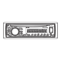
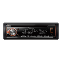
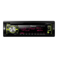
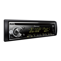
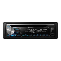
Illustrations of the unit's exterior with numbered parts.
Exploded view of the CD mechanism module with parts list.
Schematic for the tuner amplifier section handling vehicle interface signals.
Schematic showing the system regulator components within the tuner amp.
Schematic diagram for the Bluetooth (BT) related circuitry.
Schematic for additional supporting circuits in the tuner amp unit.
Schematic for the interface circuit related to iPod connectivity.
Schematic for the system U-con interface circuitry.
Schematic for the mecha VD interface part of the tuner amp unit.
Schematic for the EVOL related circuitry in the tuner amp unit.
Schematic for the Lithio related circuitry in the tuner amp unit.
Schematic for external interface connections to the tuner amp.
Schematic for the power amplifier section of the tuner amp unit.
Visual representation of critical signal waveforms for diagnostic purposes.
Top and bottom view of the tuner amp unit PCB with component locations.
PCB layout for the keyboard unit, showing component placement.
PCB layout for the CD core unit, indicating component positions.
List of miscellaneous components like ICs, transistors, diodes, and inductors.
Comprehensive list of resistors and capacitors with part numbers.