This document is a service manual for the Pioneer DR-U124X-7 and DR-US124X-6 CD-ROM drive units, published in May 1995. It provides essential information for servicing and understanding these devices, including parts lists, schematic diagrams, block diagrams, and IC information.
Function Description:
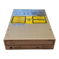
The Pioneer DR-U124X-7 and DR-US124X-6 are CD-ROM drive units designed to read CD-ROM and CD-DA (Compact Disc Digital Audio) data. The manual indicates that these models are largely similar in construction to the DR-UA124X-3/ZUC/WL, with specific differences noted in the "Contrast of Miscellaneous Parts" section. The drives feature a SCSI (Small Computer System Interface) host interface, allowing them to connect to a computer system for data transfer. They also include an audio output for playing CD-DA, with a dedicated headphone jack and volume control.
The core functionality involves a pickup assembly with a hologram laser unit that reads data from the CD. This data is then processed by a digital servo signal processor (IC301, TC9405F) and a ROM decoder (IC801, LC89512W-V79). A CPU (IC701, MB90T678) controls the overall operation, including communication with the host computer via the SCSI interface. The drive incorporates various motors for loading the disc, spinning the disc (spindle motor), and positioning the pickup (carriage motor, focus, and tracking coils).
Important Technical Specifications:
- Models Covered: DR-U124X-7 and DR-US124X-6.
- Power Requirement: DC power supplied from other system components.
- Host Interface: SCSI.
- Laser Unit: Hologram Laser Unit (LTOH46M5).
- CPU: MB90T678 (IC701).
- ROM Decoder: LC89512W-V79 (IC801).
- Digital Servo Signal Processor: TC9405F (IC301).
- RAM: 64k x 16bit (IC802, KM681000BLG-5).
- EPROM: 64k x 16bit (IC702, DYW1401 for DR-U124X-7, DYW1424 for DR-US124X-6).
- Crystal Resonators:
- X301: 33.8688MHz (for DR-U124X-7 only).
- X801: 37.2557MHz (for DR-US124X-6).
- X701: 4MHz ceramic oscillator.
- Audio Output: LPF (Low Pass Filter) for audio signal, with headphone output.
- Connectors:
- CN101: SCSI Host Interface.
- CN706: Audio Out.
- CN601: Device Configuration Jumper.
- CN201: Pickup Assembly.
- CN501: Spindle Motor Assembly.
- CN901: INSW Unit (Carriage Motor).
- JA601: Phones (Headphone Jack).
- CN703: Connector for various signals.
- CN706: Pin Header (14P).
- CN101: SCSI/Power Supply Connector.
- CN501: Connector (11P).
- CN401: KR Connector.
- CN703: Connector (3P).
- Switches:
- S902: Loading Switch.
- S901: Inside Switch.
- S702: Play Switch (for DR-U124X-7 only).
- S701: Eject Switch.
- Indicators: Busy Indicator.
- Resistors: Various types including 2-effective digit (e.g., 560 ohm, 47k ohm) and 3-effective digit (e.g., 5.62k ohm) metal film resistors, with tolerances of J=5% and K=10%.
- Capacitors: A wide range of ceramic, electrolytic, and polyester capacitors are listed, with various capacitance values and voltage ratings.
Usage Features:
- CD-ROM Data Reading: The primary function is to read data from CD-ROMs, likely for computer applications.
- CD-DA Playback: The drive supports playing audio CDs, indicated by the presence of an audio output, headphone jack (JA601), and a phone volume control (VR601). A "PLAY SW" (S702, for DR-U124X-7 only) and "EJECT SW" (S701) are also present for basic control.
- Loading Mechanism: A "LOADING SW" (S902) and "LOADING MOTOR" (DXM1077) suggest an automated disc loading mechanism.
- Device Configuration: Jumpers (CN601) are available for device configuration, which might include settings for SCSI ID or termination.
- Busy Indicator: A "BUSY INDICATOR" provides visual feedback on the drive's operational status.
Maintenance Features:
- Parts List: A comprehensive "Contrast of Miscellaneous Parts" and "PCB Parts List" are provided, detailing components for the Mother Board Assy (SCSI) (DWX1573 and DWX1592). This includes semiconductors (ICs, transistors, diodes), coils, filters, switches, relays, capacitors, resistors, and various connectors.
- Schematic Diagrams: Detailed schematic diagrams (SCH-1F, SCH-2F, SCH-3F) illustrate the electrical connections and components of the drive, including the pickup assembly, motors, control circuits, and interfaces.
- Block Diagram: A high-level block diagram (page 9) outlines the functional blocks of the drive, showing the signal flow from the pickup to the SCSI connector and audio output. This is crucial for understanding the overall system architecture and troubleshooting.
- IC Information: Detailed pin functions and block diagrams are provided for key ICs, specifically the LC89512W-V79 (IC801, ROM Decoder). This information is vital for diagnosing issues at the component level.
- Safety Precautions: The manual emphasizes the importance of using parts of identical designation, especially for components marked with a " " symbol, due to their safety factor.
- Part Availability Notes: It explicitly states that parts marked "NSP" (Not in Spare Parts List) are generally unavailable, and parts marked with " " may have longer delivery times or be unavailable. This is important for managing repair expectations.
- Resistor Ordering Guide: Instructions are provided on how to convert resistance values into code form for ordering, distinguishing between 2-effective digit and 3-effective digit resistors.
- PCB Layout Diagrams: PCB diagrams (PCB-1F) are included, showing the component placement on the Mother Board Assy (SCSI) from the "pink colored foil side." It also notes that the PCB is double-sided, which is important for tracing connections. The diagrams are intended to be used in conjunction with the schematic diagrams for accurate component identification and troubleshooting.
- Model-Specific Differences: The manual highlights that while many parts are common, specific components like the EP-ROM (IC702), Mother Board Assy (SCSI), and certain labels/packaging may differ between the DR-U124X-7 and DR-US124X-6 models. This is crucial for ensuring the correct parts are used for each specific model.
- Caution for Replacement Parts: A note on the schematic diagram (page 6) advises: "CAUTION: FOR CONTINUED PROTECTION AGAINST RISK OF FIRE, REPLACE ONLY WITH SAME TYPE NO. IC4, S1.0, AND/OR PIONEER PART NO. DKH1016." This highlights critical components that require exact replacements for safety.