Do you have a question about the Pioneer DV-09 and is the answer not in the manual?
| Type | DVD Player |
|---|---|
| Video Output | Composite, S-Video, Component |
| Video DAC | 10-bit / 27MHz |
| Dynamic Range | 100 dB |
| Signal to Noise Ratio | 115 dB |
| Audio Output | Analog, Digital (Coaxial, Optical) |
| Supported Disc Formats | DVD, CD, Video CD |
| Output Resolution | 480i |
| Audio DAC | 24-bit/96 kHz |
Essential safety measures for USA models to protect users and technicians.
Procedure to measure product leakage current to ensure safety.
Notice about replacement parts with special safety characteristics and potential hazards.
Diagrams and list of items included in the product packaging.
List of parts included in the product packaging.
Comparison of parts for DV-09/KU/CA and DV-S9/L/TA models.
Comparison of parts for DV-09/KU/CA and DV-S9/L/TA models.
Parts list for the bottom view, part 1 of 2.
Comparison of parts for DV-09/KU/CA and DV-S9/L/TA models.
Parts list for the bottom view, part 2 of 2.
Comparison of parts for DV-09/KU/CA and DV-S9/L/TA models.
Parts list for the front panel section.
Comparison of parts for DV-09/KU/CA and DV-S9/L/TA models.
Parts list for the loading mechanism assembly.
Parts list for the servo mechanism assembly.
Overall connection diagram for key assemblies.
Schematic diagram for the DVD Main Assy.
Schematic diagram of the DVD Main Assy, part 1 of 4.
Schematic diagram of the DVD Main Assy, part 2 of 4.
Schematic diagram of the DVD Main Assy, part 3 of 4.
Schematic diagram of the DVD Main Assy, part 4 of 4.
Schematics for front panel related assemblies.
Schematic diagram for the Audio Assy.
Schematic diagram for the DOUT Assy.
Schematic diagram for the DIRB Assy (DV-S9 only).
Notes on interpreting PCB and schematic diagrams.
PCB connection diagrams for LOMB, LOSB, INSB, and FGSB assemblies.
PCB connection diagram for the VOUT Assy.
PCB connection diagram for the AUDIO Assy.
PCB connection diagram for the DIRB Assy.
List of all PCB assemblies and their part numbers.
Parts list and comparison for TRSA Assy.
Parts list and comparison for FLKB Assy.
Parts list and comparison for AUDIO Assy.
Parts list and comparison for DOUT Assy.
Parts lists for various PCB assemblies.
Lists of capacitors, resistors, and coils with part numbers.
Lists of resistors, connectors, fittings, and specific assembly parts.
Parts lists for KPWSB, LEDB, STBY, and DRSB assemblies.
Parts lists for DOUT and AUDIO assemblies.
Parts lists for SYPS and DIRB (DV-S9 only) assemblies.
Parts lists for resistors, other components, and specific assemblies.
Lists adjustment points on PCB and mechanism parts.
Location of adjustment points on the DVD Main and Audio circuit boards.
Location and procedure for mechanism adjustment screws.
Steps to enter, operate, and exit the test mode.
Explanation of the TV monitor display during test mode operations.
Adjustment procedures for mechanism assembly parts.
Adjustment points on the DVD Main and Audio circuit boards.
Location and procedure for mechanism adjustment screws.
Procedure for coarse adjustment of tangential and radial skew.
Procedure for adjusting DVD jitter.
Procedures for adjusting Y, C, Cb, and Cr signal levels.
Procedures for adjusting VCO offset and master clock.
Steps to enter, operate, and exit the test mode.
Explanation of the TV monitor display during test mode operations.
General information and lists of parts.
List of Integrated Circuits (ICs) with pin functions.
Information about the display panel, including grid and pin assignments.
Flowchart and diagrams for overall disassembly steps.
Step-by-step disassembly procedures for major components and assemblies.
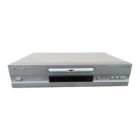
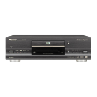
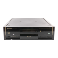
Description of front and rear panel controls and connections.
Overview of controls and indicators on the front panel.
Description of rear panel connections and audio/video outputs.
General specifications including system, laser, power, weight, and dimensions.
Specifications for video and audio output connections and levels.
Specifications for digital audio outputs and various terminals.