Do you have a question about the Pioneer DV-2750-S and is the answer not in the manual?
Details specifications for laser diodes used in DVD and CD playback.
Details specific laser safety mechanisms and precautions during operation.
General technical specifications including system, power, dimensions, and operating conditions.
Overall system block diagram illustrating major components and connections.
Procedures for diagnosing issues and operating the unit in test mode.
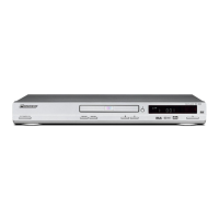
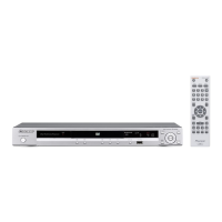
| Brand | Pioneer |
|---|---|
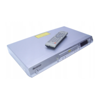
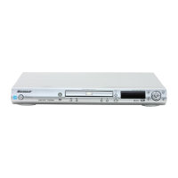
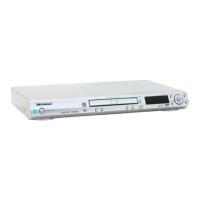
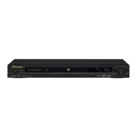
| Model | DV-2750-S |
| Category | DVD Player |
| Language | English |