EasyManua.ls Logo

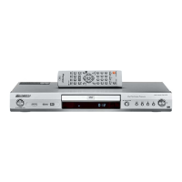
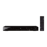
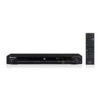
Pioneer DV-470-S Service Manual

Pioneer DV-470-S
88 pages
To Next Page IconTo Next Page
Page #1 background imageLoading...
Page #1 background image
ORDER NO.
PIONEER CORPORATION 4-1, Meguro 1-chome, Meguro-ku, Tokyo 153-8654, Japan
PIONEER ELECTRONICS (USA) INC. P.O. Box 1760, Long Beach, CA 90801-1760, U.S.A.
PIONEER EUROPE NV Haven 1087, Keetberglaan 1, 9120 Melsele, Belgium
PIONEER ELECTRONICS ASIACENTRE PTE. LTD. 253 Alexandra Road, #04-01, Singapore 159936
PIONEER CORPORATION 2004
DV-470-S
RRV2959
DVD PLAYER
DV-470-S
DV-470-K
THIS MANUAL IS APPLICABLE TO THE FOLLOWING MODEL(S) AND TYPE(S).
Model Type Power Requirement Region No.
Serial No.
Confirm 3rd & 4th
alphabetical letters.
DV-470-S WYXCN AC220-240V 2 &&TE######$$
DV-470-S WYXCN/FG AC220-240V 2 &&TE######$$
DV-470-S WVXCN AC220-240V 2 &&TE######$$
DV-470-K WYXCN AC220-240V 2 &&TE######$$
DV-470-K WYXCN/FG AC220-240V 2 &&TE######$$
For details, refer to "Important symbols for good services".
T-ZZE JUNE 2004 printed in Japan

Questions and Answers:

Pioneer DV-470-S Specifications

General IconGeneral
TypeDVD Player
Video OutputComposite, S-Video, Component
Video DAC10-bit / 27MHz
Progressive ScanYes
Video Output SystemNTSC, PAL
Remote ControlYes
ColorSilver
Disc Formats SupportedDVD-Video, DVD-R/RW, CD, CD-R/RW
Audio OutputDigital Optical, Digital Coaxial
Audio DAC24-bit
Output Resolution480p

Summary

SAFETY INFORMATION

LASER DIODE CHARACTERISTICS

Details laser diode output power and wavelength for DVD and CD.

1. SPECIFICATIONS

2. EXPLODED VIEWS AND PARTS LIST

3. BLOCK DIAGRAM AND SCHEMATIC DIAGRAM

4. PCB CONNECTION DIAGRAM

5. PCB PARTS LIST

6. ADJUSTMENT

6.1 ADJUSTMENT ITEMS AND LOCATION

Identifies adjustment items and their physical locations on the mechanism.

6.3 NECESSARY ADJUSTMENT POINTS

Outlines adjustment points required when replacing specific mechanism parts.

6.4 TEST MODE

Explains how to enter, operate, and exit the player's test mode.

7. GENERAL INFORMATION

7.1 DIAGNOSIS

Covers general diagnostic procedures and information for troubleshooting.

7.1.7 TROUBLE SHOOTING

Offers a guide to diagnose and resolve common operational symptoms.

7.1.10 DISASSEMBLY

Provides step-by-step instructions for disassembling the unit's main components.

7.2 IC

Block Diagram

Pin Function

7.3 DISC / CONTENT FORMAT PLAYBACK COMPATIBILITY

8. PANEL FACILITIES

Related product manuals