Do you have a question about the Pioneer DV-585A-S and is the answer not in the manual?
Details on laser diode power output and wavelength for DVD and CD.
Information on laser warning labels and their locations on the unit.
Notes on laser diode operation, test modes, and exposure hazards.
Guidelines for safe repair practices, including part usage and soldering.
Procedures for maintaining product performance through proper adjustments.
Guidance on using specified lubricants, glues, and replacement parts.
Instructions for cleaning optical pickups, heads, and lenses for optimal performance.
Procedures for setting shipping mode and installing shipping screws.
Overview of system, power requirements, dimensions, operating conditions, and weight.
Details on S-video output level and connector type.
Specifications for the video output level and connector.
Parameters for the stereo audio output, including level and channels.
Specifications for multi-channel audio output, including level and channels.
Frequency response, S/N ratio, dynamic range, and THD for digital audio.
Information on coaxial and optical digital output connectors.
Output levels for Y, Pb, and PR color signals and connector type.
List of included accessories such as cables, remote, and batteries.
Diagram showing packaging components and their assembly order.
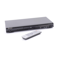
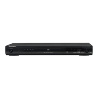
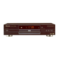
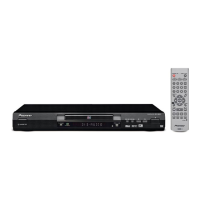
Diagram illustrating the external parts of the DVD player.
Detailed diagram of the DVD mechanical section and its components.
High-level overview of the system's major functional blocks and interconnections.
Detailed wiring diagram showing connections between main assemblies.
Schematic diagram for the first part of the DVD Main PCB assembly.
Schematic diagram for the second part of the DVD Main PCB assembly.
Schematic diagram for the third part of the DVD Main PCB assembly.
Schematic diagram for the fourth part of the DVD Main PCB assembly.
Schematic diagram for the fifth part of the DVD Main PCB assembly.
Schematic diagram for the sixth part of the DVD Main PCB assembly.
Diagrams and component details for the Operation 2 PCB.
Diagrams and component details for the Operation PCB.
Schematic diagram for the first half of the Power PCB.
Schematic diagram for the second half of the Power PCB.
Oscilloscope waveforms for key signals on the DVD MT PCB.
Connection diagrams for the Loading Motor and SW PCBs.
Component layout diagram for the DVD MT PCB (Side A).
Component layout diagram for the Operation PCB (Side A).
Component layout diagram for the Operation 2 PCB (Side A).
Component layout diagram for the Power PCB (Side A).
Part numbers for major assemblies like PCBs and mechanical units.
List of semiconductor components on the DVD MT PCB.
List of semiconductor components on the Operation PCB.
List of switches and relays on the Operation 2 PCB.
Part numbers for connectors, jacks, and jumpers.
List of resistor components.
List of parts specific to the Power PCB Assy.
Parts list for the SW PCB Assy (no service parts listed).
Parts list for the Loading Motor PCB Assy (no service parts listed).
Procedure for safely removing and installing the DVD deck, including soldering notes.
Steps to power on the unit for test mode operation.
Procedure for inserting and closing the disc tray for testing.
Instructions for entering and operating in the Play test mode.
Steps to exit the test mode and power off the unit.
Details on test mode entry, display, and functional operations.
Key sequence to enter the test mode from the remote control.
Procedure to exit the test mode by turning off the power.
Key sequence to turn on the laser diodes for DVD and CD testing.
Procedure for removing a disc without power using manual gear rotation.
Steps to cancel the parental control password.
Precautions and measures for preventing static electricity damage during repair.
Overview of diagnostic functions and information display.
Details on the information displayed during the test mode.
Functionality of shortcut keys available during normal playback.
Details on how model information is displayed and its contents.
Operations and displays within the unit's service mode.
Procedure to diagnose laser diode degradation by measuring voltages.
Guide to diagnosing and resolving common operational problems and symptoms.
Step-by-step instructions for disassembling the unit and removing major boards.
Procedures for disassembling the DVD deck and removing specific parts.
Steps to remove the disc tray assembly.
Instructions for removing the traverse assembly.
Procedure to remove the loading motor PCB and belt.
Steps for removing rack loading, main gear, and pulley gear components.
Instructions for removing the clamper assembly.
Procedures for removing traverse holder and insulators.
Steps for removing various mechanical and PCB components.
Guidelines for correctly folding and installing FFC cables.
Pinout diagram and function description for the MT1389EE/B2-L IC.
High-level functional block diagram of the MPEG/MICON/RF-AMP microcomputer.
Internal block diagram of the LA6565 motor drive IC.
Block diagram of the PT6315 FIP drive IC for display control.
Overview of supported disc types and media formats.
Details on compatible CD-R/RW formats and playback features.
Information on supported DVD-R/RW formats and playback capabilities.
Compatibility details for MP3, WMA, and other compressed audio formats.
Explanation of Windows Media Audio (WMA) format and playback support.
Information on DivX video format and player compatibility.
Details on supported subtitle file formats and display settings.
Information on compatible DivX video file extensions and certifications.
Specifications for supported JPEG image file formats and resolutions.
Notes on compatibility issues with discs created using personal computers.
Diagram and description of the front panel controls and indicators.
Explanation of the front panel display indicators and their meanings.
Diagram and description of all remote control buttons and their functions.
List of jigs used for diagnosis, including the service remote control.
List of test discs for diagnosing DVD-Video playback.
List of test discs for diagnosing CD playback.
List of recommended lubricants and glues for servicing.
Procedures and tools for cleaning unit components like pickup lenses.
| Type | DVD Player |
|---|---|
| Progressive Scan | Yes |
| Audio DAC | 192 kHz / 24-bit |
| Surround Sound | Dolby Digital, DTS |
| Video Output | Composite, S-Video, Component |
| Output Resolution | 480p, 720p, 1080i |
| HDMI Output | No |
| Media Type | DVD, CD |
| Audio Output | Optical |