Do you have a question about the Pioneer DV-600AV-S and is the answer not in the manual?
| Audio formats supported | MP3, WMA |
|---|---|
| Image formats supported | JPG |
| Video formats supported | DivX, WMV |
| Playback formats | DivX, WMV, MP3, WMA, JPEG |
| Dimensions (WxDxH) | 420 x 215.5 x 49.5 mm |
| Power requirements | 220 - 240 V/ 50/60 Hz |
| Audio decoders | DTS |
| Frequency range | 4 - 44 Hz |
| Signal-to-Noise Ratio (SNR) | 115 dB |
| Total Harmonic Distortion (THD) | 0.0023 % |
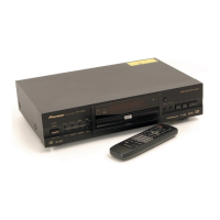
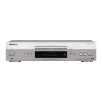
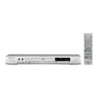
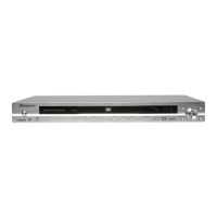
| Device type | DVD player |
| Product color | Silver |
| Disc types supported | CD |
| Number of optical discs | 1 discs |
| USB 2.0 ports quantity | USB 2.0 ports have a data transmission speed of 480 Mbps, and are backwards compatible with USB 1.1 ports. You can connect all kinds of peripheral devices to them. |
| Digital audio coaxial out | 1 |
| Power consumption (standby) | 0.8 W |
| Power consumption (typical) | 12 W |
| Depth | 215.5 mm |
|---|---|
| Width | 420 mm |
| Height | 49.5 mm |
| Weight | 1800 g |
Details laser power output and wavelength for DVD and CD discs.
Information regarding laser radiation warning labels on the unit.
Guidelines for safe repair practices, including part usage and soldering.
Procedures for maintaining product performance and specifications.
Guidance on using specified lubricants and adhesives for repairs.
Proper cleaning procedures for optical parts and lenses.
Instructions for setting shipping mode before product shipment.
Information on using lead-free solder and soldering iron specifications.
Steps for removing and installing the DVD deck, including safety precautions.
Procedure to remove a disc when the unit is not powered on.
Steps to cancel the 4-digit parental control password.
Measures to protect against static electricity during repair.
Lists all accessories included with the product.
Covers general unit specs like power, dimensions, and AV connector pin assignments.
Details output levels for component, S-video, video, audio, HDMI, and digital signals.
Overview of supported disc types including DualDisc and CD-R/RW.
Compatibility details for DVD+R/RW and DVD-R/RW discs.
Details on MP3, WMA, AAC, and WMV audio file support.
Information on DivX video file support and versions.
Details on compatible JPEG image formats and extensions.
Information on potential issues with discs created on personal computers.
Identifies and describes front panel controls and indicators.
Identifies and describes the functions of all remote control buttons.
Procedures and recommended checks to perform after servicing the unit.
Diagram showing the physical location of various PCB assemblies within the unit.
Lists required jigs for diagnosis and operation checks.
Lists recommended lubricants and glues with their part numbers.
Instructions for cleaning pickup lenses before shipping.
Shows how different PCBs are interconnected via connectors and wiring.
High-level functional block diagram of the unit's main components.
Block diagram specific to the DVD loader and MPEG processing.
Illustrates the power supply circuit and voltage regulation.
Flowcharts for diagnosing common power and deck issues.
Lists symptoms associated with specific IC failures on the DVD MT PCB.
Procedure to diagnose laser diode degradation on the pickup assembly.
Step-by-step guide to enter and exit the service mode.
Details on service mode entry, release, and laser diode activation.
Explains the meaning of information displayed in the service mode.
Describes shortcut key functions for playback and service modes.
Details on ID Address, Error Rate, and EDC/ID error history.
Instructions for removing external mechanical parts and PCBs.
Detailed steps for removing individual parts from the DVD deck.
Steps to create and perform a DVD firmware update.
Exploded view and parts list for the product packaging.
Exploded view illustrating exterior components and their assembly.
Exploded view and parts list for the DVD mecha section.
Schematic diagram for the DVD MT PCB, part 1 of 7.
Schematic for DVD MT PCB, part 2 of 7, showing FLASH IC.
Schematic for DVD MT PCB, part 3 of 7, detailing pickup and loader circuits.
Schematic for DVD MT PCB, part 4 of 7, showing audio DAC and video driver.
Schematic for DVD MT PCB, part 5 of 7, focusing on video driver IC.
Schematic for DVD MT PCB, part 6 of 7, showing HDMI and interface signals.
Schematic for DVD MT PCB, part 7 of 7, detailing power supply connections.
Schematics for Operation 1 and 2 PCBs, including front panel interface.
Primary side schematic of the power supply PCB.
Secondary side schematic of the power supply PCB.
Schematic for the USB PCB, showing connections to DVD and power PCBs.
Displays oscilloscope wave forms for various test points on the DVD MT PCB.
Component layout for Side A of the DVD MT PCB.
Component layout for Side B of the DVD MT PCB.
Component layouts for inserted and chip-mounted parts of Operation 1 & 2 PCBs.
Component layout for inserted parts of the Power PCB.
Component layout for chip-mounted parts of the Power PCB.
Component layouts for Loading Motor PCB (inserted and chip-mounted).
Component layouts for USB PCB (inserted and chip-mounted).
Component layout for the Switch (SW) PCB.
Lists main PCB assemblies and their corresponding part numbers.
Lists Semiconductors, Resistors, and Others for the DVD MT PCB.
Lists Semiconductors, Switches, and Others for Operation PCBs.
Lists resistor components for the Power PCB.
Lists Semiconductors and Others for the USB PCB.