EasyManua.ls Logo

Pioneer DV-717 User Manual

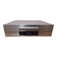
Pioneer DV-717
65 pages
To Next Page IconTo Next Page
Page #1 background imageLoading...
Page #1 background image
ORDER NO.
PIONEER ELECTRONIC CORPORATION 4-1, Meguro 1-Chome, Meguro-ku, Tokyo 153-8654, Japan
PIONEER ELECTRONICS SERVICE, INC. P.O. Box 1760, Long Beach, CA 90801-1760, U.S.A.
PIONEER ELECTRONIC (EUROPE) N.V. Haven 1087, Keetberglaan 1, 9120 Melsele, Belgium
PIONEER ELECTRONICS ASIACENTRE PTE. LTD. 501 Orchard Road, #10-00 Wheelock Place, Singapore 238880
PIONEER ELECTRONIC CORPORATION 1998
RRV2010
1. SAFETY INFORMATION
......................................
2
2. EXPLODED VIEWS AND PARTS LIST
................
3
3. SCHEMATIC DIAGRAM
.....................................
10
4. PCB CONNECTION DIAGRAM
..........................
33
5. PCB PARTS LIST
...............................................
45
6. ADJUSTMENT
....................................................
50
CONTENTS
THIS MANUAL IS APPLICABLE TO THE FOLLOWING MODEL(S) AND TYPE(S).
Type
Model
DV-717
WY
WY/RD
WY/RE
AC220 – 240V
AC220 – 240V
AC220 – 240V
Power Requirement
Region restriction code
(region number)
T – ZZM OCT. 1998 Printed in Japan
Remarks
7. GENERAL INFORMATION
................................
56
7.1 PARTS
.........................................................
56
7.1.1 IC
...........................................................
56
7.2 DISASSEMBLY
...........................................
59
7.3 BLOCK DIAGRAM
.......................................
60
7.4 CIRCUIT DESCRIPTION
............................
62
7.4.1 VIDEO SIGNAL PROCESSING BLOCK
..
62
8. PANEL FACILITIES AND SPECIFICATIONS
....
63
• Refer to the service guide RRV2004 for DV-515.
2
4
5
DV-717
DVD PLAYER
STANDBY
STANDBY/ON
DIGITAL
DATA OFF
DNR FL OFF
ACOUSTIC DAMPER MECHANISM
0
7
1¢
£¥8
Question and Answer IconNeed help?

Do you have a question about the Pioneer DV-717 and is the answer not in the manual?

Pioneer DV-717 Specifications

General IconGeneral
BrandPioneer
ModelDV-717
CategoryDVD Player
LanguageEnglish

Summary

Safety Information

Exploded Views and Parts List

Packing List Details

Lists the parts included in the product's packaging.

Exterior Section Overview

Front Panel Section Details

Bottom Section Components

Loading Mechanism Assembly

Servo Mechanism Assembly

Schematic Diagrams

FLKY, PWSB, and DILB Assemblies Schematics

Schematic diagrams for FLKY, PWSB, and DILB assemblies.

DVDM Assembly Schematics (1/3)

Schematic diagram for the DVDM assembly, part 1 of 3.

DVDM Assembly Schematics (2/3)

Schematic diagram for the DVDM assembly, part 2 of 3.

DVDM Assembly Schematics (3/3)

Schematic diagram for the DVDM assembly, part 3 of 3.

AVJB Assembly Schematics (1/2)

Schematic diagram for the AVJB assembly, part 1 of 2.

AVJB Assembly Schematics (2/2)

Schematic diagram for the AVJB assembly, part 2 of 2.

DNRB Assembly Schematics (1/2)

Schematic diagram for the DNRB assembly, part 1 of 2.

DNRB Assembly Schematics (2/2)

Schematic diagram for the DNRB assembly, part 2 of 2.

SCRB Assembly Schematics

Schematic diagram for the SCRB assembly.

Power Supply and MSWB Assemblies Schematics

Schematic diagrams for the power supply and MSWB assemblies.

PCB Connection Diagrams

DVDM Assembly PCB Layout

PCB layout diagram for the DVDM assembly.

AVJB Assembly PCB Layout

PCB layout diagram for the AVJB assembly.

DNRB Assembly PCB Layout

PCB layout diagram for the DNRB assembly.

SCRB Assembly PCB Layout

PCB layout diagram for the SCRB assembly.

Power Supply and MSWB Assemblies PCB Layouts

PCB layout diagrams for the power supply and MSWB assemblies.

PCB Parts List

Adjustment Procedures

Adjustment Items and Location

Details adjustment points on specific PCBs for calibration.

Jigs and Measuring Instruments

Lists necessary jigs and measuring instruments for adjustments.

Necessary Adjustment Points

Identifies when adjustments are needed for specific PCB replacements.

Electrical Adjustment Procedures

Step-by-step procedures for electrical adjustments including clock, VCO, and signal levels.

General Information

Parts List and IC Pin Functions

Lists and details various parts, including IC pin functions for key components.

Disassembly Guide

Step-by-step instructions for disassembling the product.

System Block Diagram

High-level block diagram illustrating system architecture and component interactions.

Circuit Description and Signal Processing

Explanation of circuit operations, particularly video signal processing.

Panel Facilities and Specifications

Remote Control Functions

Explains the functions of the remote control buttons for user operation.

Display Window Information

Describes the information displayed on the unit's display window.

General Product Specifications

Includes power, weight, dimensions, audio, video, and terminal specifications.

Included Accessories

Lists the accessories provided with the product.

Related product manuals