EasyManua.ls Logo

Pioneer FH-P6050UB/XJ User Manual

Pioneer FH-P6050UB/XJ
100 pages
To Next Page IconTo Next Page
Page #1 background imageLoading...
Page #1 background image
ORDER NO.
PIONEER CORPORATION 4-1, Meguro 1-chome, Meguro-ku, Tokyo 153-8654, Japan
PIONEER ELECTRONICS (USA) INC. P.O. Box 1760, Long Beach, CA 90801-1760, U.S.A.
PIONEER EUROPE NV Haven 1087, Keetberglaan 1, 9120 Melsele, Belgium
PIONEER ELECTRONICS ASIACENTRE PTE. LTD. 253 Alexandra Road, #04-01, Singapore 159936
PIONEER CORPORATION 2008
FH-P800BT/XJ/UC
CRT4134
CD RECEIVER
FH-P800BT
/XJ/UC
FH-P8000BT
/XJ/UC
CD RDS RECEIVER
FH-P80BT
/XJ/EW5
CD RECEIVER
FH-P6050UB
/XJ/ES
This service manual should be used together with the following manual(s):
Model No. Order No. Mech.Module Remarks
CX-3240 CRT4050 S10.5COMP2-
iPod/USB
CD Mech. Module : Circuit Descriptions, Mech. Descriptions, Disassembly
For details, refer to "Important Check Points for Good Servicing".
K-ZZZ. FEB. 2008 Printed in Japan
FH-P800BT/XJ/UC
Question and Answer IconNeed help?

Do you have a question about the Pioneer FH-P6050UB/XJ and is the answer not in the manual?

Pioneer FH-P6050UB/XJ Specifications

General IconGeneral
BrandPioneer
ModelFH-P6050UB/XJ
CategoryCar Stereo System
LanguageEnglish

Summary

SAFETY INFORMATION

General Safety Cautions

General cautions for service technicians and product safety.

Laser Diode and Servicing Precautions

Precautions for laser diode handling and general servicing safety.

Important Check Points for Good Servicing

Product Safety Guidelines

Guidelines for conforming to regulations and using specified parts for safe repair.

SERVICE PRECAUTIONS

General Service Precautions

General safety and handling precautions for servicing the unit.

CONNECTION DIAGRAM

General Unit Wiring

Diagram for connecting unit components.

Power Cable Connection Notes

Specifics on power cable connection.

BASIC ITEMS FOR SERVICE

Check Points After Servicing

Procedures and items to confirm after servicing.

BLOCK DIAGRAM

Combi PWB Unit Block Diagram

Overall block diagram of the Combi PWB unit.

DIAGNOSIS

Operational Flowchart

Flowchart for the power-on operation sequence.

Error Code List

List of error codes, their causes, and potential solutions.

USB and iPod Error Messages

Error messages related to USB audio player and iPod connectivity.

CONNECTOR FUNCTION DESCRIPTION

Connector Pin Layouts

Pin assignments for various connectors on the unit.

SERVICE MODE OPERATIONS

CD Test Mode Procedures

Cautions, entry/exit, and flowchart for CD test mode.

Display Test Mode Usage

How to operate the display test mode.

DISASSEMBLY PROCEDURES

Case and Keyboard Unit Removal

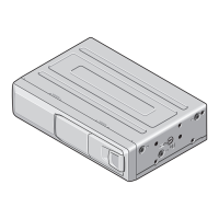
Steps for removing outer casing and keyboard.

SETTING AND ADJUSTMENT

Grating Check After Pickup Replacement

Procedure to check grating angle after replacing the pickup unit.

CD MECHANISM MODULE

SCHEMATIC DIAGRAMS

Overall and Combi PWB Unit Schematics

High-level and Combi PWB unit schematic.

PCB CONNECTION DIAGRAMS

ELECTRICAL PARTS LIST

Related product manuals