EasyManua.ls Logo

Pioneer FH-P800BT User Manual

Pioneer FH-P800BT
100 pages
To Next Page IconTo Next Page
Page #1 background imageLoading...
Page #1 background image
ORDER NO.
PIONEER CORPORATION 4-1, Meguro 1-chome, Meguro-ku, Tokyo 153-8654, Japan
PIONEER ELECTRONICS (USA) INC. P.O. Box 1760, Long Beach, CA 90801-1760, U.S.A.
PIONEER EUROPE NV Haven 1087, Keetberglaan 1, 9120 Melsele, Belgium
PIONEER ELECTRONICS ASIACENTRE PTE. LTD. 253 Alexandra Road, #04-01, Singapore 159936
PIONEER CORPORATION 2008
FH-P800BT/XJ/UC
CRT4134
CD RECEIVER
FH-P800BT
/XJ/UC
FH-P8000BT
/XJ/UC
CD RDS RECEIVER
FH-P80BT
/XJ/EW5
CD RECEIVER
FH-P6050UB
/XJ/ES
This service manual should be used together with the following manual(s):
Model No. Order No. Mech.Module Remarks
CX-3240 CRT4050 S10.5COMP2-
iPod/USB
CD Mech. Module : Circuit Descriptions, Mech. Descriptions, Disassembly
For details, refer to "Important Check Points for Good Servicing".
K-ZZZ. FEB. 2008 Printed in Japan
FH-P800BT/XJ/UC
Question and Answer IconNeed help?

Do you have a question about the Pioneer FH-P800BT and is the answer not in the manual?

Pioneer FH-P800BT Specifications

General IconGeneral
BluetoothYes
CD PlayerYes
MP3 PlaybackYes
WMA PlaybackYes
AAC PlaybackYes
Display TypeLCD
Preamp Outputs3 (Front, Rear, Subwoofer)
AUX InputYes
USB InputYes
iPod ControlYes
Remote ControlYes
Tuner TypeAM/FM
Power Output50W x 4

Summary

SAFETY INFORMATION

General Safety Cautions and Warnings

Covers general safety, warnings, laser precautions, and specific operational cautions.

Service Best Practices and Guidelines

Product Safety and Servicing Procedures

Covers product safety, using parts, modifications, soldering, screws, connectors, wiring, etc.

Service Precautions and Notes

General Service Precautions

Covers regulations, power off, ESD, IC handling, and mechanism operation.

Product Specifications Overview

General, Audio, and Media Specifications

Details power, audio output, load impedance, equalizer, CD player, USB, and media formats.

Head Unit Control Panel Overview

Front Panel Button Functions

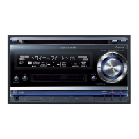
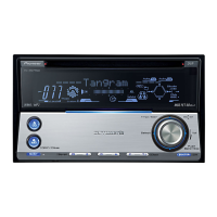
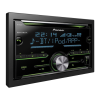
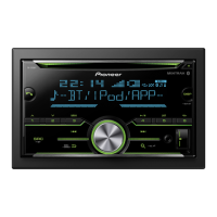
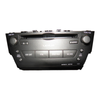
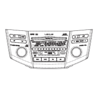
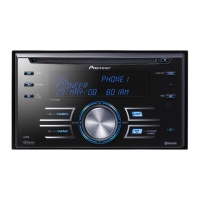
Explains the function of each button and control on the head unit's front panel.

Remote Control Operation Guide

Remote Control Button Functions

Describes the operation and function of each button on the remote control.

Display Indication Guide

Main Display and Indicator Meanings

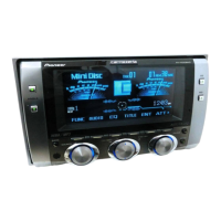
Explains the main display section and the meaning of various status indicators.

System Connection Diagrams

Main Unit Wiring Diagram

Illustrates the main unit's connection to power, speakers, antenna, microphone, and other accessories.

Power Cable Connection Guide

Power Cable Wiring Instructions

Details power cable connection steps and notes for vehicle compatibility.

Basic Service Checks and Procedures

Post-Servicing Verification Checklist

Lists essential checks to ensure product quality and customer satisfaction after servicing.

PCB Component Layouts

Main PCB and Module Locations

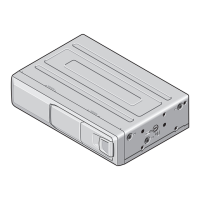
Shows the physical location of key PCBs and modules within the unit for service.

Service Tools and Cleaning Procedures

Jigs, Grease, and Cleaning Tools

Lists specific jigs, grease, and cleaning agents required for servicing.

Diagnostic Flowcharts and Information

Power-On Operational Flowchart

Illustrates the sequence of operations and checks performed during the unit's power-on sequence.

Error Code Troubleshooting Guide

Error Code List and Potential Causes

Provides a comprehensive list of error codes, their classification, and common causes for troubleshooting.

USB and iPod Error Message Solutions

Troubleshooting USB/iPod Connectivity Errors

Details specific error messages related to USB and iPod connectivity and their resolution steps.

Connector Pinout Descriptions

External Connector Pin Assignments

Explains the pin layout and function for all external connectors on the unit.

Service Mode Operations

CD Test Mode Procedures and Cautions

Guides on entering and performing adjustments in the CD test mode, including safety precautions.

Display Test Mode Operations

Display Test Mode Activation and Usage

Explains how to access and utilize the display test mode for visual checks.

Bluetooth Test Mode Functions

Bluetooth Memory Clear and Reset Procedures

Describes how to clear Bluetooth memory and reset the microprocessor for troubleshooting.

Bluetooth Mobile Phone Connectivity Test

BT-Compliant Phone Test Setup and Cautions

Covers testing Bluetooth connectivity with mobile phones, including setup and warnings.

Bluetooth Spectrum Analyzer Test Procedure

2.4 GHz Spectrum Analyzer Test Setup

Details the process for testing Bluetooth output levels using a 2.4 GHz spectrum analyzer.

Unit Disassembly Instructions

Removing External Case and CD Mechanism

Step-by-step guide for removing the outer case, grille assembly, and CD mechanism module.

Internal Component Removal Procedures

Removing Case, Cord Assy, and Antenna Unit

Instructions for removing the case unit, cord assembly, and antenna unit.

PWB Unit Removal Guide

Removing the Combi PWB Unit

Details the procedure for safely removing the main combination PCB unit.

Mechanism Unit Handling and Frame Removal

Proper Handling and Removing Upper/Lower Frames

Explains how to hold the mechanism unit and remove its frame assemblies.

CD Core Unit and Pickup Module Removal

Removing CD Core Unit and Pickup Assembly

Provides instructions for detaching the CD core unit and the pickup assembly.

Pickup Unit Adjustment and Verification

Grating Angle Check After PU Replacement

Details the procedure for checking and adjusting the grating angle after replacing the pickup unit.

PCL Output Signal Verification

Confirming PCL Output for Clock Signal

Explains the method to verify the PCL output signal and its frequency.

Exploded Views and Parts Lists

Packing Exploded View and Parts

Presents the exploded view and parts list for the product's packaging.

Exterior Parts Identification - Part 1

Exterior Exploded View Diagram (Part 1)

Shows the exploded view of external components, numbered for parts list reference.

Exterior Parts Identification - Part 2

Exterior Exploded View Diagram (Part 2)

Displays another exploded view of external components, continuing the parts list.

CD Mechanism Module Exploded Views

CD Mechanism Exploded View and Parts List

Provides the exploded view and parts list for the CD mechanism module assembly.

System Schematic Diagrams

Overall System Connection Diagram

A high-level block diagram showing the interconnection of major system components.

Keyboard Unit Schematic and Layout

Keyboard Unit PCB Layout and Component Details

Illustrates the component placement and schematic for the keyboard unit PCB.

CD Mechanism Module Circuit Schematics

CD Mechanism Module Internal Circuit Diagram

Detailed schematic showing the internal circuitry of the CD mechanism module.

Bluetooth Unit Schematic Diagram

Bluetooth Unit Internal Circuit Diagram

Provides the schematic diagram illustrating the internal circuitry of the Bluetooth unit.

Waveform Analysis for Core Unit

CD Core Unit Waveform Examples and Interpretation

Displays and explains various waveforms generated during CD operation for analysis.

PCB Connection Diagrams

Combi PWB Unit Connection Points

Shows the connection points and component layout on the Combi PWB unit.

Keyboard Unit PCB Layout

Keyboard Unit Component Placement Diagram

Illustrates the top-side component placement on the keyboard unit PCB.

CD Core Unit PCB Layout

CD Core Unit Component Placement Diagram

Shows the top-side component placement on the CD core unit PCB.

Bluetooth Unit PCB Layout

Bluetooth Unit Component Placement Diagram

Illustrates the top-side component placement on the Bluetooth unit PCB.

Antenna Unit Diagrams

Antenna Unit Side A and Side B Layouts

Displays the layout diagrams for the antenna unit on both sides.

Electrical Parts List - Miscellaneous Components

Miscellaneous Electrical Component Details

Lists miscellaneous electrical parts including ICs, transistors, and other components.

Electrical Parts List - Resistors (Part 1)

Resistor Component Details (Part 1)

Lists resistors with their part numbers, categorized by symbol and number.

Electrical Parts List - Capacitors and Resistors (Part 2)

Capacitor and Resistor Component Details (Part 2)

Lists capacitors and resistors with their part numbers.

Related product manuals