EasyManua.ls Logo

Pioneer FX-MG8247ZT/ES User Manual

Pioneer FX-MG8247ZT/ES
152 pages
To Next Page IconTo Next Page
Page #1 background imageLoading...
Page #1 background image
ORDER NO.
CRT3272
ES300
AUDIO SYSTEM
HEAD UNIT
CRT3272
PUB.NO.
Manufactured for TOYOTA
by PIONEER CORPORATION
VEHICLE DESTINATION
PRODUCED
AFTER
OEM PARTS No. ID No. PIONEER MODEL No.
LEXUS ES300 U.S.A., CANADA June 2004 86120-33512 P6850 FX-MG8247ZT/UC
LEXUS ES300 U.S.A., CANADA June 2004 86120-33522 P6851 FX-MG8747ZT/UC
LEXUS ES300 GENERAL ARER June 2004 86120-33531 P7835 FX-MG8247ZT/ES
LEXUS ES300 MIDDLE NEAR EAST June 2004 86120-33541 P7834 FX-MG8247ZT/Q1

Table of Contents

Question and Answer IconNeed help?

Do you have a question about the Pioneer FX-MG8247ZT/ES and is the answer not in the manual?
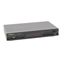
Pioneer FX-MG8247ZT/ES Specifications

General IconGeneral
ModelFX-MG8247ZT/ES
CategoryCar Receiver
Display TypeLCD
BluetoothYes
USB PortYes
Auxiliary InputYes
Remote ControlYes
EqualizerYes
Max Power Output50W x 4
Radio TunerFM/AM

Summary

SAFETY INFORMATION

Service Precaution

Precautions to be observed during servicing the unit.

2. EXPLODED VIEWS AND PARTS LIST

2.5 SERVICE MECHANISM UNIT(G1)

Exploded view and parts list for the service mechanism unit.

2.6 CASSETTE MECHANISM MODULE

Exploded view and parts list for the cassette mechanism module.

3. BLOCK DIAGRAM AND SCHEMATIC DIAGRAM

3.1 BLOCK DIAGRAM(FX-MG8247ZT/UC,FX-MG8747ZT/UC)

Block diagram illustrating system interconnections for specific models.

3.2 BLOCK DIAGRAM(FX-MG8247ZT/ES,FX-MG8247ZT/Q1)

Block diagram illustrating system interconnections for specific models.

5. ELECTRICAL PARTS LIST

6. ADJUSTMENT

6.1 JIG CONNECTION DIAGRAM

Diagram showing jig connections for adjustment procedures.

6.2 TUNER AND DOLBY NR ADJUSTMENT

Procedures for tuning and Dolby NR adjustments.

AM NOISE CANCELER ADJUSTMENT

Procedure for adjusting the AM noise canceler.

6.3 CHECKING THE GRATING AFTER CHANGING THE PICKUP UNIT

Procedure to check pickup unit grating after replacement.

7. GENERAL INFORMATION

7.1 DIAGNOSIS

Information related to diagnosing system issues.

7.1.1 TEST MODE

Instructions for entering and using the test mode for diagnosis.

7.1.3 DISASSEMBLY

Step-by-step instructions for disassembling the unit.

7.1.2 AVC-LAN DIAGNOSIS MODE

Procedure for using the AVC-LAN diagnosis mode.

Diagnosis code table

Table listing diagnosis codes and their meanings.

Related product manuals