EasyManua.ls Logo

Pioneer F-208 Service Manual

Pioneer F-208
21 pages
To Next Page IconTo Next Page
Page #1 background imageLoading...
Page #1 background image
ORDER NO.
PIONEER ELECTRONIC CORPORATION 4-1, Meguro 1-Chome, Meguro-ku, Tokyo 153-8654, Japan
PIONEER ELECTRONICS SERVICE, INC. P.O. Box 1760, Long Beach, CA 90801-1760, U.S.A.
PIONEER ELECTRONIC (EUROPE) N.V. Haven 1087, Keetberglaan 1, 9120 Melsele, Belgium
PIONEER ELECTRONICS ASIACENTRE PTE. LTD. 253 Alexandra Road, #04-01, Singapore 159936
PIONEER ELECTRONIC CORPORATION 1999
RRV2161
T – ZZE JUNE 1999 Printed in Japan
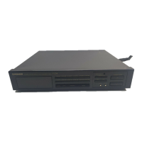
FM/AM DIGITAL-SYNTHESIZER TUNER
F-208
CONTENTS
1. SAFETY INFORMATION ..................................... 2
2. EXPLODED VIEWS AND PARTS LIST ............... 3
3. BLOCK DIAGRAM AND SCHEMATIC DIAGRAM
......................................................... 6
4. PCB CONNECTION DIAGRAM ......................... 10
5. PCB PARTS LIST .............................................. 14
6. ADJUSTMENT................................................... 16
7. GENERAL INFORMATION ................................ 17
7.1 IC ................................................................. 17
8. PANEL FACILITIES AND SPECIFICATIONS..... 18
THIS MANUAL IS APPLICABLE TO THE FOLLOWING MODEL(S) AND TYPE(S).
Type
Model
F-208
Power Requirement
HL O AC220 - 230V
SDB O AC110/120 - 127/220/240V With the voltage selector
Remarks
STANDBY/ON
RF ATT
MPX
CHARACTER
BAND
CLASS
DIRECT
TUNING
TUNING
MEMORY
12345
6
789
0/10
FM/
AM DIGITAL-SYNTHESIZER TUNER
X¿<?˘
Î
MODE
MODE
DISPLAY
MODE
MEMORY
SCAN

Other manuals for Pioneer F-208

Questions and Answers:

Pioneer F-208 Specifications

General IconGeneral
BrandPioneer
ModelF-208
CategoryCar Receiver
LanguageEnglish

Summary

Safety Information

Model-Specific Safety Notices

Safety notices, fuse symbols, and leakage current tests for Canadian and US models.

Product Safety Component Guidance

Advice on replacing safety-critical components to prevent hazards.

Exploded Views and Parts Lists

Packing Components Overview

Exploded view and parts list for packing components.

Exterior Components and Listings

Exploded view of exterior parts and their listing.

PCB Assemblies and Contrast Table

List of PCB assemblies and contrast table for model differences.

Diagrams and Schematics

Block and Connection Diagrams

Overall block diagram and connection diagram of the tuner unit.

Assembly Schematics

Schematic diagrams for Main, Display, and Standby assemblies.

PCB Connection Diagrams

Diagram Interpretation Notes

Notes on interpreting PCB connection diagrams and symbols.

Main, Display, and Standby Assembly Diagrams

PCB connection diagrams for Main, Display, and Standby assemblies.

PCB Parts List

Parts Ordering and Notes

Notes on ordering parts, including NSP parts and resistance value conversion.

PCB Assembly Listings

List of PCB assemblies with part numbers for HL and SDB models.

Adjustment

General Information

IC Pin Function Details

Pin function list for the PDG231A System Control IC.

Panel Facilities and Specifications

Front Panel Controls and Indicators

Description of front panel controls and indicators.

Technical Specifications

Detailed technical specifications for FM, Audio, and miscellaneous sections.

Related product manuals