Do you have a question about the Pioneer GM-4000F/X1R/EW and is the answer not in the manual?
General warnings about safety and product repair by qualified technicians.
Health and safety warning regarding lead and chemicals in product components.
Compliance with regulations and adherence to safety instructions during servicing.
Explanation of symbols indicating important service procedures like safety, adjustments, and cleaning.
Details the voltage range and type for the unit's power supply.
Lists the current draw under various operating conditions.
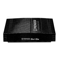
Provides the physical size specifications of the amplifier.
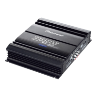
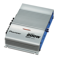
Specifies the peak power output capabilities of the amplifier.
Outlines the range of audio frequencies the amplifier can reproduce.
Indicates the amplifier's performance in terms of signal clarity and noise reduction.
Specifies the allowable speaker impedance for optimal performance.
Details the components included in the product packaging and their arrangement.
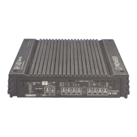
Illustrates the external parts of the amplifier and their assembly.
Lists the part numbers for items included in the product's packaging.
Lists available owner's manuals and their corresponding part numbers and languages.
Lists the part numbers for the external components of the amplifier.
Provides a high-level overview of how various components and circuits are connected.
Details the component layout and connections on the amplifier's printed circuit board.
Lists the different unit designations and their corresponding part numbers.
Lists miscellaneous electronic components like ICs, transistors, diodes, and switches with their part numbers.
Lists part numbers for chip resistors used in the unit.
Lists part numbers for chip capacitors used in the unit.
Provides information for diagnosing potential issues with the unit.
Step-by-step instructions on how to disassemble the amplifier unit.
Instructions on how to adjust amplifier gain to match the car stereo output.
Explains the function and behavior of the power indicator light.
Guidance on using the BFC switch to reduce beat noise during MW/LW broadcasts.
How to select the correct filter setting based on connected speakers.
Instructions for setting the input select switch for two-channel or four-channel input.