This document is a service manual for the Pioneer GM-600 and GM-620 ES power amplifiers, designed for car audio systems. It provides detailed information for qualified service technicians regarding the connection, disassembly, and electrical components of the device, along with important safety warnings and technical specifications.
Function Description
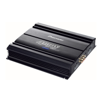
The Pioneer GM-600 and GM-620 ES are power amplifiers intended to boost the audio signal from a car stereo to drive speakers. They are designed to enhance the sound quality and volume in a vehicle's audio system. The manual covers two main models: UC (U.S. and Canada) and EW (Europe and other regions), with some variations in connection and parts. The amplifier unit includes an input level attenuator, a mute circuit, and a power amplifier section. It also features a system control terminal for integration with the car's electrical system, allowing for automatic power on/off with the ignition or car stereo.
Important Technical Specifications
The specifications provided are for the GM-600/UC model, but many are likely shared or similar for the GM-620 ES.
- Power Source: 14.4 V DC (10.8-15.6 V allowable), negative grounding type. This indicates the amplifier is designed for standard 12V automotive electrical systems.
- Max. Current Consumption: 6.5 A. This is an important figure for determining the power requirements from the car's electrical system and for fuse selection.
- Dimensions: 140 (W) x 32 (H) x 100 (D) mm [5-1/2 (W) x 1-1/4 (H) x 4 (D) in.]. These compact dimensions suggest it's designed to fit in various locations within a vehicle.
- Weight: 0.5 kg (1.1 lbs.) (Leads for wiring not included). The lightweight design is beneficial for car installations.
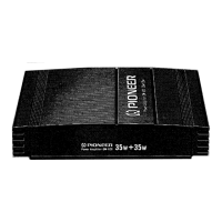
- Maximum Power Output: 35 W x 2. This is the peak power the amplifier can deliver per channel.
- Continuous Power Output: 18 W x 2 (at 4Ω, 20-20,000 Hz, 0.5% THD). This is a more realistic measure of the amplifier's sustained power output under specified conditions (4-ohm load, full audio frequency range, and a low total harmonic distortion).
- Load Impedance: 4Ω (2-8Ω allowable). This specifies the range of speaker impedances the amplifier can safely drive. Using speakers outside this range could damage the amplifier.
- Frequency Response: 10-50,000 Hz (+0 dB, -1 dB). A wide frequency response indicates the amplifier can reproduce a broad range of audio frequencies, from deep bass to very high treble, with minimal deviation.
- Signal-to-Noise Ratio: 94 dB (IHF-A network). A high signal-to-noise ratio indicates that the amplifier produces very little background noise relative to the audio signal, resulting in cleaner sound.
- Distortion: 0.015% (at 10W, 1kHz). A very low total harmonic distortion (THD) figure signifies high fidelity, meaning the amplifier reproduces the audio signal accurately with minimal added distortion.
- Input Level: 0.2-2 V/7kΩ. This specifies the range of input signal voltage the amplifier can accept and its input impedance.
Usage Features
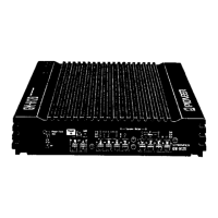
- Connectivity: The manual details two primary connection methods:
- UC, ES Model: Uses RCA pin jacks for input from the car stereo, providing a high-quality, low-noise connection. It also includes connections for left and right speakers, a blue lead for system control (auto-antenna relay or system control terminal), a red lead for ignition switch-controlled 12V DC power, and a black lead for grounding to the car chassis.
- EW Model: Uses DIN sockets for input from the car stereo, which is common in European car audio systems. Similar to the UC/ES model, it includes connections for speakers, a yellow lead for the car's lighting switch (illumination), a red lead for ignition-controlled power, and a black lead for grounding.
- Input Level Adjustment: The amplifier features an input level control on the back. This allows users to match the amplifier's input sensitivity to the output level of their car stereo. If the sound is too low, the control should be turned clockwise; if the sound distorts, it should be turned counterclockwise. This feature is crucial for optimizing sound quality and preventing distortion.
- System Control Terminal: The amplifier can be integrated with the car's electrical system to turn on and off automatically with the car stereo or ignition, providing convenience and preventing battery drain.
- Illumination Switching (EW Model): The EW model includes a connection for the car's lighting switch, allowing the amplifier's illumination (if any) to synchronize with the car's dashboard lights.
Maintenance Features
- Disassembly Instructions: The manual provides clear steps for disassembling the unit, specifically for removing the heat sink. This is a common first step for accessing internal components for repair or inspection.
- Remove four screws A and four screws B.
- Remove the heat sink.
- Schematic Circuit Diagrams: Detailed schematic diagrams are provided for both UC/ES and EW models, showing the internal circuitry of the amplifier unit. These diagrams are essential for troubleshooting and repairing electronic faults, identifying components, and understanding signal paths.
- Connection Diagrams: Comprehensive connection diagrams illustrate how the amplifier should be wired into the car's audio and electrical systems. These are critical for correct installation and troubleshooting wiring issues.
- Exploded View: An exploded view diagram shows all the individual parts of the amplifier and their assembly order. This is invaluable for reassembly after repairs and for identifying specific components.
- Electrical Parts List: A detailed list of electrical parts, including resistors, capacitors, ICs, transistors, and diodes, is provided with their part numbers. This list is crucial for ordering replacement parts and ensuring compatibility. It also notes that some parts may not be supplied or may have longer delivery times.
- Safety Information: The manual includes a "CAUTION" section emphasizing that it is intended for qualified service technicians due to the complexity of repairs and potential safety risks. It warns against improper repairs that could affect safety, reliability, or void the warranty.
- WARNING (Lead in Solder): A specific warning about lead in solder is included, noting its classification as a reproductive toxicant by California Health and Welfare. It advises technicians to avoid unprotected skin contact with solder and to not inhale smoke or fumes during soldering, highlighting environmental and health considerations for maintenance.
- Specifications Subject to Modification: A note indicates that specifications and design are subject to change without notice due to improvements, which is a standard disclaimer for electronic products.