Y
PIONEER’
The
Art
of
Entertainment
@
GM-202/xX1H/UC
BRIDGEABLE
POWER
AMPLIFIER
GM-20
ORDER
NO.
CRT1643
xXIN/UC
GM-202
XIFV/EW,ES
GM-102
xIH/UC
CONTENTS
1.
SAFETY
INFORMATION(UC
MODEL)
«..-s.sccceucteees
2
2.
DISASSEMBLY
....csscscsuscsnseesctnetetenenscsctienseee
2
3.
ELECTRICAL
PARTS
LIST
cru
sssesssesstsstcesseiesenetet
3
4.
CONNECTION
DIAGRAM
(GM-202/X1H/UC,EW,ES)....5
5.
SCHEMATIC
CIRCUIT
DIAGRAM
(GM-202/X1H/UC,EW,ES)....7
6.
CONNECTION
DIAGRAM(GM-102/X
1H/UC)........
9
SPECIFICATIONS
Power
Source
...........
14.4V
DC
(10.8
—
15.6
V
allowable)
Grounding
System
oo...
eee
eeeceeeeeeeeee
Negative
type
Current
consumption
12.5
A
(at
continuous
power,
49)
Average
current
drawn.........
3.5A
(4Q
for
two
channels)
6A
(4Q
for
one
channel)
BUS
Oca
ce
stecidsetdislctescesiediecdteescsaty
ent
baaa
teenies
By
avi
case
15A
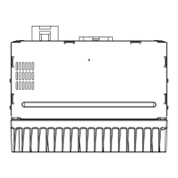
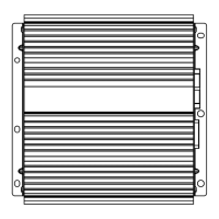
DIMENSIONS
«0...
eee
206(W)
*
50(H)
=
175(D)mm
{8-
1/8{W)
*
2(H}
x
6-7/8(D}in.}
WI
GRE
ecsscevsectscsesciacth
cxcetecniiedtsdedaverrain
wnhccspeeenies
1.9
kg
{2.2
Ibs.)
(Leads
for
wiring
not
included)
Maximum
power
output............
TOW
X
2/160W
*
1
(EIAS)
PIONEER
ELECTRONIC
CORPORAT
jleguro
1+
7,
SCHEMATIC
CIRCUIT
DIAGRAM
(GM-102/X1H/UC)........
11
8.
EXPLODED
VIEW...
9.
PACKING
METHOD
10.
OPERATIONS
AND
CONNECTION
(GM-202/X
TH/UC)........
7
11.
OPERATIONS
AND
CONNECTION
(GM-102/X1H/UC)........
19
Continuous
power
output
sevens
35W
x
2(at
14.4V,
49,
20
—
20,000
Hz,
0.08%
THD)
BOW
x
Tat
14.4V,
2,
20
—
20,000
Hz,
0.8%
THD)
SOW
x
2{at
14.4V,
20,
20
—
20,000
Hz,
0.8%
THD)
25W
X
2{at
12V,
4Q,
20
—
20,000
Hz,
0.08%
THD)
55W
*
tat
12V,
4Q,
20
—
20,000
Hz,
0.8%
THD)
35W
*
2fat
12V,
2Q,
20
—
20,000
Hz,
0.8%
THD)
Load
impedance...
eecceeeeeee
4Q
(2
—
8
allowable)
-.10
—-
50,000
Hz
(+0dB,
-1dB)
105
dB
(INF
—
A
network)
60
dB(1kHz)
RCA:
0.4
—~
2V/22kQ
Frequency
response...
Signal-to-noise
ratio
..
Separation
input
level/impedance
..
Input
level/impedance
(GM-X102)
decervidesnd
saves
sovtsedes
Speaker:
1.6
—
8
V/40kQ
ome,
Meguro-ku,
Tokyo
153,
Japan
PIONEER
ELECTRONICS
SERVICE
INC.
P.O.Box
1760,
Long
Beach,
California
90801
U.S.A.
PIONEER
ELECTRONICS
OF
CANADA,
INC.
300
Allstate
Parkway
Markham,
Ontario
L8R
OP2
Canada
PIONEER
ELECTRONIC
[EUROPE]
N.V.
Haven
1087
Keetberglaan
1,
9120
Melsele,
Beigium
PIONEER
ELECTRONICS
AUSTRALIA
PTY.LTD.
178-184
Boundary
Road,
Braeside,
Victoria
3195,
Australia
TEL:103}580-9911
©
PIONEER
ELECTRONIC
CORPORATION
1995
K-FFP.
JAN.
1995
Printed
in
Japan