EasyManua.ls Logo

Pioneer GM-6500F/XZUC User Manual

Pioneer GM-6500F/XZUC
30 pages
To Next Page IconTo Next Page
Page #1 background imageLoading...
Page #1 background image
ORDER NO.
PIONEER CORPORATION 1-1, Shin-ogura, Saiwai-ku, Kawasaki-shi, Kanagawa 212-0031, Japan
PIONEER ELECTRONICS (USA) INC. P.O. Box 1760, Long Beach, CA 90801-1760, U.S.A.
PIONEER EUROPE NV Haven 1087, Keetberglaan 1, 9120 Melsele, Belgium
PIONEER ELECTRONICS ASIACENTRE PTE. LTD. 253 Alexandra Road, #04-01, Singapore 159936
PIONEER CORPORATION 2011
GM-6500F/XZUC
CRT4709
BRIDGEABLE FOUR-CHANNEL POWER AMPLIFIER
GM-6500F
/XZUC
GM-6500F/XZEW5
GM-6500F/XZES
For details, refer to "Important Check Points for Good Servicing".
K-ZZZ APR. 2011 Printed in Japan
Question and Answer IconNeed help?

Do you have a question about the Pioneer GM-6500F/XZUC and is the answer not in the manual?

Pioneer GM-6500F/XZUC Specifications

General IconGeneral
BrandPioneer
ModelGM-6500F/XZUC
CategoryAmplifier
LanguageEnglish

Summary

Product Safety Information and Warnings

Service Precautions

General Service Precautions

Detailed service precautions covering IC handling, screw tightening, and transistor mounting.

Soldering Notes for Repairs

Guidance on using lead-free solder and appropriate soldering iron temperatures for repairs.

Product Specifications

Detailed Technical Specifications

Detailed technical specifications for the GM-6500F/XZUC and its variants.

Basic Service Requirements

Post-Service Checkpoints

Procedures to verify product quality and resolve customer complaints post-repair.

Servicing Lubricants and Glues

List of lubricants and glues with part numbers required for servicing.

Block Diagram Overview

Troubleshooting and Diagnosis

Connector Functions Description

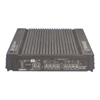
Identification and function of various connectors on the amplifier.

Service Mode Information

Unit Disassembly Procedures

Case Removal Steps

Step-by-step guide for safely removing the outer case of the amplifier.

PCB Kit Removal Steps

Instructions for carefully removing the main Printed Circuit Board (PCB) Kit.

Settings and Adjustments

Exploded Views and Parts Lists

Packaging Exploded View and Parts

Exploded view and parts list of the product's packaging materials.

Exterior Components Exploded View

Exploded view and parts list for the external components of the amplifier.

Schematic Diagrams

PCB Kit Schematic Overview

Overview page for the schematic diagram of the main PCB Kit.

PCB Connection Diagrams

PCB Kit Connection Layout

Detailed connection diagram for the main PCB Kit, showing component placement.

Electrical Parts List

Related product manuals