EasyManua.ls Logo

Pioneer GM-X622 X1R/UC User Manual

Pioneer GM-X622 X1R/UC
22 pages
To Next Page IconTo Next Page
Page #1 background imageLoading...
Page #1 background image
PIONEER ELECTRONIC CORPORATION 4-1, Meguro 1-Chome, Meguro-ku, Tokyo 153-8654, Japan
PIONEER ELECTRONICS SERVICE INC. P.O.Box 1760, Long Beach, CA 90801-1760 U.S.A.
PIONEER ELECTRONIC [EUROPE] N.V. Haven 1087 Keetberglaan 1, 9120 Melsele, Belgium
PIONEER ELECTRONICS ASIACENTRE PTE.LTD. 501 Orchard Road, #10-00, Wheelock Place, Singapore 238880
C PIONEER ELECTRONIC CORPORATION 1998
K-ZED. FEB.1998 Printed in Japan
ORDER NO.
CRT2190
BRIDGEABLE POWER AMPLIFIER
Se
r
v
i
c
e
M
a
nu
a
l
GM-X622 X1R/UC
GM-X622/X1R/UC
CONTENTS
1. SAFETY INFORMATION ............................................2
2. EXPLODED VIEWS AND PARTS LIST.......................2
3. SCHEMATIC DIAGRAM .............................................6
4. PCB CONNECTION DIAGRAM ................................12
5. ELECTRICAL PARTS LIST ........................................14
6. ADJUSTMENT..........................................................17
7. GENERAL INFORMATION .......................................18
7.1 IC .........................................................................18
7.2 DISASSEMBLY ...................................................19
7.3 BLOCK DIAGRAM ..............................................20
8. OPERATIONS AND SPECIFICATIONS.....................21
GM-X622 X1R/EW
GM-X622 X1R/ES
GM-X522 X1R/UC
Question and Answer IconNeed help?

Do you have a question about the Pioneer GM-X622 X1R/UC and is the answer not in the manual?

Pioneer GM-X622 X1R/UC Specifications

General IconGeneral
Channels2
RMS Power at 4 Ohms60W x 2
Frequency Response10Hz - 50kHz
Signal to Noise Ratio100 dB
MOSFET Power SupplyYes
Speaker Level InputsYes
CrossoverVariable HPF/LPF
Weight6.6 lbs
RMS Power at 2 Ohms75 Watts x 2
Bridged RMS Power at 4 Ohms150 Watts x 1
Bass Boost0-12dB
Input Sensitivity200mV - 6.5V

Summary

Safety Information

Exploded Views and Parts List

Product Packing Parts List

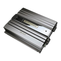
Details components related to the product's packaging and lists part numbers.

External Components Parts List

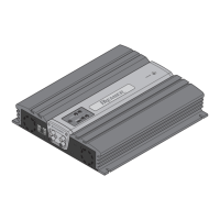
Lists external components with their corresponding part numbers and diagrams.

Schematic Diagram

Overall Amplifier Connection Diagram

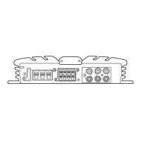
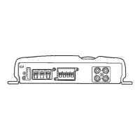
Presents an overview connection diagram for the amplifier unit.

PCB Connection Diagram

Amplifier Unit PCB Connection Diagram

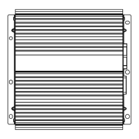
Illustrates the physical layout of components on the amplifier's printed circuit board.

Electrical Parts List

Adjustment

General Information

Integrated Circuit (IC) Information

Provides specific information and diagrams for the integrated circuits used in the unit.

Operations and Specifications

Amplifier Specifications

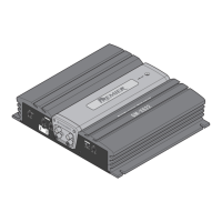
Outlines the technical specifications, performance, and physical characteristics of the amplifier.

Amplifier Operations

Explains the user-accessible controls, features, and operational modes of the amplifier.

Related product manuals