EasyManua.ls Logo

Pioneer GM-X422 User Manual

Pioneer GM-X422
20 pages
To Next Page IconTo Next Page
Page #1 background imageLoading...
Page #1 background image
ORDER NO.
CRT2167
Se
r
v
i
c
e
M
a
nu
a
l
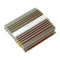
BRIDGEABLE POWER AMPLIFIER
PIONEER ELECTRONIC CORPORATION 4-1, Meguro 1-Chome, Meguro-ku, Tokyo 153-8654, Japan
PIONEER ELECTRONICS SERVICE INC. P.O.Box 1760, Long Beach, CA 90801-1760 U.S.A.
PIONEER ELECTRONIC [EUROPE] N.V. Haven 1087 Keetberglaan 1, 9120 Melsele, Belgium
PIONEER ELECTRONICS ASIACENTRE, PTE.LTD. 501 Orchard Road, #10-00, Wheelock Place, Singapore 238880
C PIONEER ELECTRONIC CORPORATION 1998
K-ZEU. JAN. 1998 Printed in Japan
GM-X422 X1R/UC, ES, EW
CONTENTS
1. SAFETY INFORMATION ............................................1
2. EXPLODED VIEWS AND PARTS LIST.......................2
3. SCHEMATIC DIAGRAM .............................................6
4. PCB CONNECTION DIAGRAM ..................................8
5. ELECTRICAL PARTS LIST ........................................12
6. ADJUSTMENT..........................................................14
7. GENERAL INFORMATION .......................................15
7.1 DISASSEMBLY ...................................................15
8. OPERATIONS AND SPECIFICATIONS.....................16
1. SAFETY INFORMATION
This service manual is intended for qualified service technicians; it is not meant for the casual do-it-yourselfer.
Qualified technicians have the necessary test equipment and tools, and have been trained to properly and safely repair
complex products such as those covered by this manual.
Improperly performed repairs can adversely affect the safety and reliability of the product and may void the warranty.
If you are not qualified to perform the repair of this product properly and safely, you should mot risk trying to do so
and refer the repair to a qualified service technician.
UC model
CAUTION
This service manual is intended for qualified service technicians; it is not meant for the casual do-it-yourselfer.
Qualified technicians have the necessary test equipment and tools, and have been trained to properly and safely repair
complex products such as those covered by this manual.
Improperly performed repairs can adversely affect the safety and reliability of the product and may void the warranty.
If you are not qualified to perform the repair of this product properly and safely; you should not risk trying to do so
and refer the repair to a qualified service technician.
W
ARNING
Lead in solder used in this product is listed by the California Health and Welfare agency as a known reproductive toxi-
cant which may cause birth defects or other reproductive harm (California Health & Safety Code, Section 25249.5).
When servicing or handling circuit boards and other components which contain lead in solder, avoid unprotected skin
contact with the solder. Also, when soldering do not inhale any smoke or fumes produced.
GM-X322 X1R/UC
Question and Answer IconNeed help?

Do you have a question about the Pioneer GM-X422 and is the answer not in the manual?

Pioneer GM-X422 Specifications

General IconGeneral
BrandPioneer
ModelGM-X422
CategoryAmplifier
LanguageEnglish

Summary

Safety Information and Precautions

Cautionary Notes

Service manual intended for qualified technicians; emphasizes safety and reliability concerns.

Lead Solder Warning

Warning about lead in solder and precautions for handling circuit boards and components.

Exploded Views and Parts Identification

Packing Section Exploded View

Exploded view and parts list for the packing section of the amplifier.

Exterior Section Exploded View

Exploded view illustrating the external components of the amplifier unit.

Schematic Diagrams

Mother PCB Schematic Diagram

Schematic diagram for the Mother PCB, detailing component layout and connections.

Isolator PCB Schematic Diagram

Schematic diagram for the Isolator PCB, illustrating its circuit layout.

PCB Connection Diagrams

Mother PCB Connection Diagram

PCB connection diagram for the Mother PCB, showing component placement.

Isolator PCB Connection Diagram

PCB connection diagram for the Isolator PCB, illustrating component layout.

Electrical Parts List

Electrical Parts: Miscellaneous

List of miscellaneous electronic components including ICs, transistors, and passive parts.

Electrical Parts: Resistors

Comprehensive list of resistors with circuit symbols, part names, and part numbers.

Electrical Parts: Capacitors

List of capacitors with circuit symbols, part names, and part numbers.

Adjustment Procedures

General Information and Disassembly

Unit Disassembly Guide

Step-by-step guide for disassembling the amplifier, including case and amp unit removal.

Operations and Unit Setup

Setting the Amplifier Unit

Guide for setting up and configuring the amplifier's operational features and controls.

Connection Diagrams

Connection Diagram: GM-X422/X1R/UC

Connection diagram specifically for the GM-X422/X1R/UC model.

Connection Diagram: GM-X422/X1R/ES, EW

Connection diagrams for GM-X422/X1R/ES and GM-X422/X1R/EW models.

Connection Diagram: GM-X322/X1R/UC

Connection diagram for the GM-X322/X1R/UC model.

Power Terminal Wiring

Instructions for connecting the power terminal of the amplifier to the vehicle's battery.

Speaker Terminal Wiring

Instructions for connecting speaker wires to the amplifier's terminals.

Connecting Speaker Wires

Speaker Wiring: UC Models

Speaker wire connection modes for UC models, including two-channel and three-channel setups.

Speaker Wiring: ES Models

Speaker wire connection modes for ES models, covering two-channel and one-channel setups.

Speaker Wiring: EW Models

Speaker wire connection modes for EW models, covering two-channel and one-channel setups.
Technical Specifications

Related product manuals