EasyManua.ls Logo

Pioneer GM-X434 User Manual

Pioneer GM-X434
25 pages
To Next Page IconTo Next Page
Page #1 background imageLoading...
Page #1 background image
PIONEER ELECTRONIC CORPORATION 4-1, Meguro 1-Chome, Meguro-ku, Tokyo 153-8654, Japan
PIONEER ELECTRONICS SERVICE INC. P.O.Box 1760, Long Beach, CA 90801-1760 U.S.A.
PIONEER ELECTRONIC [EUROPE] N.V. Haven 1087 Keetberglaan 1, 9120 Melsele, Belgium
PIONEER ELECTRONICS ASIACENTRE PTE.LTD. 253 Alexandra Road, #04-01, Singapore 159936
C PIONEER ELECTRONIC CORPORATION 1999
K-ZZA. JAN. 1999 Printed in Japan
ORDER NO.
CRT2358
BRIDGEABLE FOUR-CHANNEL POWER AMPLIFIER
GM-X434 X1R/UC
CONTENTS
1. SAFETY INFORMATION ............................................2
2. EXPLODED VIEWS AND PARTS LIST.......................2
3. SCHEMATIC DIAGRAM .............................................6
4. PCB CONNECTION DIAGRAM ................................12
5. ELECTRICAL PARTS LIST ........................................16
6. ADJUSTMENT..........................................................20
7. GENERAL INFORMATION .......................................20
7.1 IC .........................................................................20
7.2 DISASSEMBLY ...................................................22
8. OPERATIONS AND SPECIFICATIONS.....................23
GM-X334 X1R/UC,EW,ES
GM-X434/X1R/UC
Question and Answer IconNeed help?

Do you have a question about the Pioneer GM-X434 and is the answer not in the manual?

Pioneer GM-X434 Specifications

General IconGeneral
BrandPioneer
ModelGM-X434
CategoryAmplifier
LanguageEnglish

Summary

SAFETY INFORMATION

EXPLODED VIEWS AND PARTS LIST

PACKING SECTION PARTS LIST

Lists parts for the product packaging and accessories.

EXTERIOR SECTION PARTS LIST

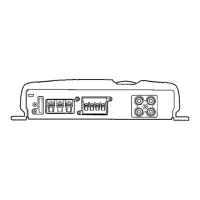
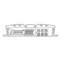
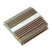
Details external components and their part numbers.

SCHEMATIC DIAGRAM

OVERALL CONNECTION DIAGRAM

Provides a high-level overview of the circuit connections.

PCB CONNECTION DIAGRAM

AMP UNIT PCB LAYOUT

Shows component placement for the main amplifier unit PCB.

ELECTRICAL PARTS LIST

GENERAL INFORMATION

PARTS INFORMATION

Provides details on specific part types and their designations.

INTEGRATED CIRCUITS (ICs)

Lists integrated circuits used in the unit with their part numbers.

DIAGNOSIS AND DISASSEMBLY

DISASSEMBLY PROCEDURES

Step-by-step instructions for taking the unit apart.

OPERATIONS AND SPECIFICATIONS

UNIT OPERATIONS

Explains how to use the unit's controls and features.

UNIT SPECIFICATIONS

Lists technical details, power ratings, and performance data.

CONNECTING THE UNIT

Related product manuals