Do you have a question about the Pioneer GM-X404 and is the answer not in the manual?
General precautions for qualified service technicians regarding product safety.
Warning about lead in solder and its reproductive toxicity.
Steps to remove the outer case and front panel of the unit.
Procedure for detaching the amplifier unit from the heat sink.
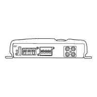
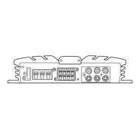
Details controls for power, input selection, filters, and bass boost.
Important cautions for safe and proper installation of the unit.
Guidelines to prevent damage from improper speaker wiring or impedance.
Connects the special red battery wire to the amplifier's positive terminal.
Connects the ground wire to the vehicle body or chassis.
Specifies fuse ratings for power wire and amplifier.
Safety precautions to prevent injury and damage during installation.
Details controls for power, input selection, and filters.
Important cautions for safe and proper installation of the unit.
Guidelines to prevent damage from improper speaker wiring or impedance.
Connects the special red battery wire to the amplifier's positive terminal.
Connects the ground wire to the vehicle body or chassis.
Specifies fuse ratings for power wire and amplifier.
Safety precautions to prevent injury and damage during installation.
| Channels | 4 |
|---|---|
| Frequency Response | 10 Hz - 50 kHz |
| Signal to Noise Ratio | 100 dB |
| Crossover | Yes |
| THD at RMS Power | 0.05% |
| Low Pass Filter | 50 Hz - 250 Hz |
| High Pass Filter | 50 Hz - 250 Hz |