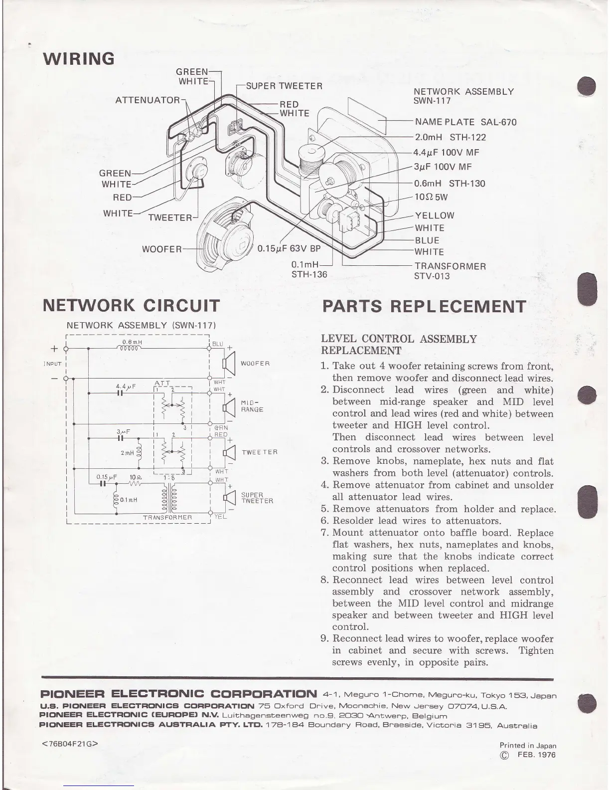
WIRING
GRE
WHI
ATTENUATOR
GREEN
WHITE
RE
WHITE
TWEETER
WOOFER
NETWORK
CIRCUIT
NETWORK ASSEMBLY
(SWN-I
1 7)
SUPER TWEETER
RED
WHITE
0.1mH
sTH-136
LEVEL
CONTROL
ASSEMBLY
REPLACEMENT
1. Take out 4
woofer retaining screws
from front,
then remove
woofer and
disconnect lead wires.
2. Disconnect
lead
wires
(green
and white)
between mid-range
speaker
and
MID
level
control
and lead
wires
(red
and white)
between
tweeter and HIGH
level control.
Then disconnect lead
wires between level
controls
and crossover networks.
3.
Remove
knobs,
nameplate, hex nuts
and flat
washers
from both
level
(attenuator)
controls.
4.
Remove attenuator from cabinet
and unsolder
aII
attenuator
lead
wires.
5. Remove attenuators
from holder
and
replace.
6. Resolder
lead
wires to attenuators.
7.
Mount
attenuator onto baffle board.
Replace
flat washers, hex nuts, nameplates
and knobs,
making sure
that the
knobs
indicate correct
control
positions
when replaced.
8.
Reconnect
lead
wires
between
level
control
assembly and crossover network
assembly,
between the
MID
level control
and
midrange
speaker
and between tweeter
and
HIGH
level
control.
9.
Reconnect
lead
wires to
woofer,
replace
woofer
in cabinet and secure
with screws.
Tighten
screws evenly, in
opposite
pairs.
NETWORK ASSEMBLY
SWN.I17
NAME
PLATE
SAL.67O
2.0mH
STH-122
4.41tF
100V MF
3pF 100V MF
0.6mH STH-130
10s,
5w
YELLOW
WHITE
BLUE
ITE
TRANSFORMER
STV-O13
PARTS
REPL ECEMENT
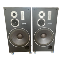
WOOFER
I-WEETER
t4lD-
RANGE
SU PER
TWEETER
PICINEEFI
ELECTFIG|NIC
COF|PCIFIATIGIN
4-1, Mesuno 1-chome,
Meguno-ku,
Tokyo 158,
Japan
U.E.
PIGINEEFI
ELECTFICTNICS CClFIPctFIATIclN
75 Oxfond Dnive,
Moonachie,
New
Jensey
O7O74,
U.S.A.
PIC|NEEFI
ELECTFICINIC
(EIJFICIPEI
N.V.
Luithagensteenweg
no.9,
2O3O
-Antwenp,
E}elgaum
PIONEEFI ELECTFICINICEi
AIJSiTFIALIA
PTY. LTEI.
178-18,4
Boundany Fload, Bnaeside,
Victonia
3'1 35, Ausrnalia
Printed
in
Japan
o
FEB.1976
<76804F21 G>
 Loading...