EasyManua.ls Logo

Pioneer PD-S705 Service Manual

Pioneer PD-S705
34 pages
To Next Page IconTo Next Page
Page #1 background imageLoading...
Page #1 background image
Y)
PIONEER’
The
Art
of
Entertainment
Service
Manual
COMPACT
DISC
PLAYER
ORDER
NO.
RRV1550
PD-3705
THIS
MANUAL
IS
APPLICABLE
TO
THE
FOLLOWING
MODEL(S)
AND
TYPE(S).
T
|__
Model
|
Power
Requirement
The
voltage
can
be
converted
by
the
pS
PD-$705
q
following
method.
HPpw
|
O__|-AC230-240V
AC220-230V,
*
Peo
iaw
i
pe
ee
*
:
Alter
the
wiring
of
the
Power-supply
block
at
the
primary
winding
of
Power-
transformer
referring
to
the
“Line
Voltage
Selection”
described
in
Service
Manual.
CONTENTS
1.
SAFETY
INFORMATION
Se
eee
ce
nee
neceectcocscacscccess
2
6.
IC
INFORMATION
Cece
eres
sees
eee
eet
deneeesenteeace
30
2.
PACKING,
EXPLODED
VIEWS
7.
FL
INFORMATION
---0++++0200000-eseeeeeeeeeees
31
AND
PARTS
LIST
oe
cece
cecceeoceccces
3
8.
BLOCK
DIAGRAM
Cae
c
cece
sete
ne
caer
snaceeesenaeasns
32
3.
SCHEMATIC
AND
9.
DISASSEMBLY/ASSEMBLY
«-++-++++-++1e0s00++
33
PCB
CONNECTION
DIAGRAMS
-+--sseeeeeee
eee
12
10.
PANEL
FACILITIES
-1:-::e:ecceeeeeeceeeeeeeeeeen
ees
34
4.
PCB
PARTS
LIST
Stele
6a:
86
G:0sb.0)p
Clare.
0ereSp0-e8'e,o
ie
6
era's
wiles
20
11.
SPECIFICATIONS
iat
said
seeie
Sao./a1.6-di0:5::6%0)419<e
ales
Sraje-ble
ned
wi
S08
34
5.
ADJUSTMENTS
OREO
O
eMC
ee
cee
Se ce
ee
ee
eds ees
eeeee
80d
eels
25
PIONEER
ELECTRONIC
CORPORATION
4-1,
Meguro
1-Chome,
Meguro-ku,
Tokyo
153,
Japan
PIONEER
ELECTRONICS
SERVICE,
INC.
P.O.
Box
1760,
Long
Beach,
CA
90801-1760,
U.S.A.
PIONEER
ELECTRONIC
(EUROPE)
N.V.
Haven
1087,
Keetberglaan
1,
9120
Melsele,
Belgium
PIONEER
ELECTRONICS
ASIACENTRE
PTE.
LTD.
501
Orchard
Road,
#10-00
Lane
Crawford
Place,
Singapore
0923
©
PIONEER
ELECTRONIC
CORPORATION
1996
sige
an
soba
Baiicacee:

Other manuals for Pioneer PD-S705

Question and Answer IconNeed help?

Do you have a question about the Pioneer PD-S705 and is the answer not in the manual?

Pioneer PD-S705 Specifications

Power IconPower
power requirementsAC 220 - 230 V, 50/60 Hz
power consumption14W
Operating Environment IconOperating Environment
operating temperature+5°C - +35°C
Audio Specifications IconAudio Specifications
frequency response2 Hz - 20 kHz
signal-to-noise ratio110 dB or more (EIAJ)
dynamic range96 dB or more (EIAJ)
harmonic distortion0.0026% or less (EIAJ)
output voltage2.0V
Weight and Dimensions IconWeight and Dimensions
weight4.2 kg
external dimensions420 (W) x 283 (D) x 125 (H) mm

Summary

Safety Information

Packing, Exploded Views and Parts List

Packing Details

Details on product packing and component types.

Exterior Section Overview

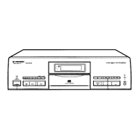
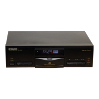
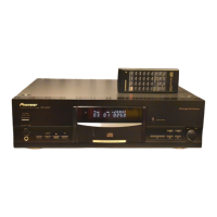
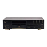
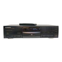
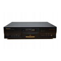
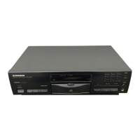
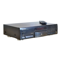
Contrasts and parts list for the exterior components of different models.

Front Panel Section Details

Information and parts list for the front panel components.

Loading Mechanism Assembly

Parts list for the loading mechanism assembly.

Servo Mechanism Assembly

Parts list for the servo mechanism assembly.

Schematic and PCB Connection Diagrams

Pickup Assembly Schematic

Schematic diagram for the pickup assembly.

Mechanism, Digital Out, Display, Switch & Servo Assemblies

Schematic diagrams for multiple unit assemblies.

Main Board & Digital Out PCB Diagram

PCB diagram for main board and digital output assemblies.

Display & Switch PCB Diagram

PCB diagram for display and switch assemblies.

PCB Parts List

Whole PCB Assembly List

List of all PCB assemblies and their part numbers.

HY and HV Type Parts

Specific parts list for HY and HV model types.

HPW and SD Type Parts

Specific parts list for HPW and SD model types.

Adjustments and Test Points

Preparation for Adjustments

Required tools and preliminary steps for adjustments.

Adjustment Locations and Procedures

Identifies VR locations and test points for adjustments.

Focus Offset and Tracking Error Checks

Procedures for checking focus offset and tracking error.

Pickup Tilt and RF Level Checks

Procedures for adjusting pickup tilt and checking RF level.

Servo Loop Gain Adjustments

Procedures for adjusting focus and tracking servo loop gain.

IC Information and Pin Functions

FL Indicator Tube Information

System Block Diagram

Disassembly and Assembly Procedures

Bonnet Removal

Steps for removing the unit's bonnet.

Tray Panel Removal

Steps for removing the disc tray panel.

Tray Panel Installation

Steps for installing the disc tray panel.

Panel Facilities and Controls

Technical Specifications

Related product manuals