70
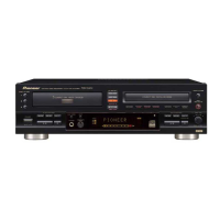
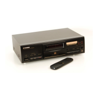
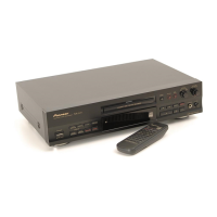
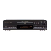
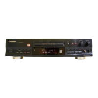
PDR-W739
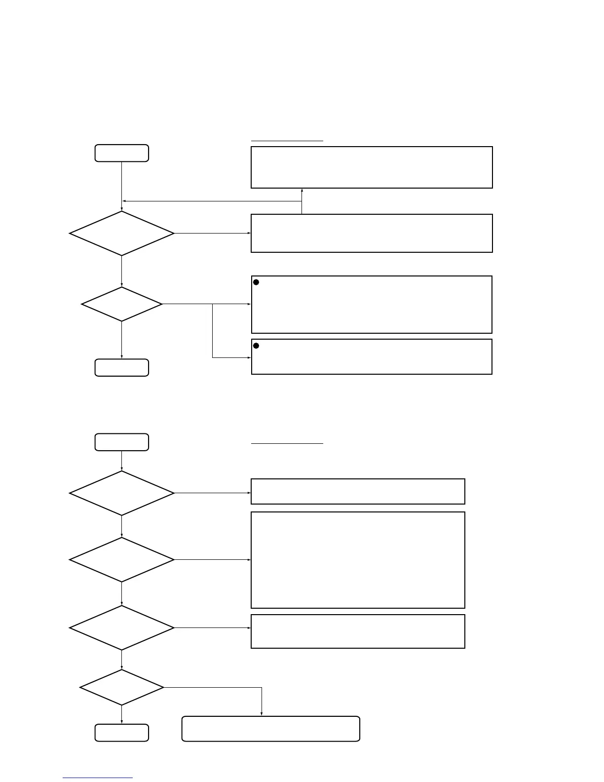
POWER ON
3CD SETUP
Is FL turn on
?
CD1, CD2, CD3
CD → CD-R
LED flash
Yes
Yes
No
No
• Blow out fuse (FU1) on the PRIMARY Assy
• Blow out thermal fuse of the power transformer
• Blow out micro-fuse (IC38) on the POWER SUPPLY Assy
• System controller (IC1402) on the MAIN Assy breaks down
• Check the following connections:
MAIN Assy - OPERATING 1 Assy
MAIN Assy - POWER SUPPLY Assy
• Reset signal (SRESET) from the system controller to the
mode controller
• Communication between the system controller and mode
controller
SYSI, SYSO, SCK, SACK, SREQ
• Check the connection between the MAIN Assy and CD-R
CORE Assy
• Blow out micro-fuse (IC33 and IC35) on the POWER
SUPPLY Assy
• Check the power supply voltage on the CD-R CORE Assy
(XPFAIL=H (normal))
• Check the communication between the mode controller
and mechanism controller
MSI, MSO, MSCK, MASK, MREQ, LREQ
• Mode controller (IC1401) on the MAIN Assy breaks down
When FL does not turn on at all:
• Check the connection between the MAIN Assy and OPERATING
1 Assy.
• Check the communication lines (FLDI, FLCL, FLCE and FLRST)
between the system controller (IC1402) and FL driver (IC701).
• FL Driver (IC701) on the OPERATING1 Assy breaks down.
Check Point
POWER ON SEQUENCE (Display System)
POWER ON
STOP
Is the mode
controller reset
release?
Is the communi-
cation between mode
controller and mecha.
controller start?
Is the communi-
cation between system
controller and mode
controller start?
Is the DISC
distinction
start?
Yes
Yes
Yes
When FL is turned on, "CD", "CD-R" or "CD-RW"
segment turns on to the right-side end of FL
No DISC
DISC exist
No
No
No
SETUP SEQUENCE (CD-R)
Check Point
When FL indication is dark or down:
• Short or open the zenner diode (D37) on the POWER SUPPLY
Assy
7.1.1 SEQUENCE AFTER THE POWER ON
7. GENERAL INFORMATION
7.1 DIAGNOSIS
 Loading...