ORDER NO.
PIONEER CORPORATION 4-1, Meguro 1-chome, Meguro-ku, Tokyo 153-8654, Japan
PIONEER ELECTRONICS SERVICE, INC. P.O. Box 1760, Long Beach, CA 90801-1760, U.S.A.
PIONEER EUROPE NV Haven 1087, Keetberglaan 1, 9120 Melsele, Belgium
PIONEER ELECTRONICS ASIACENTRE PTE. LTD. 253 Alexandra Road, #04-01, Singapore 159936
PIONEER CORPORATION 2000
c
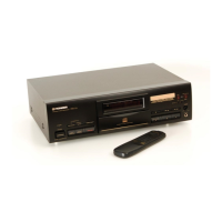
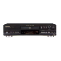
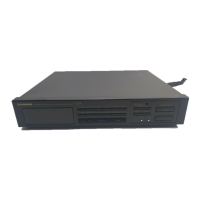
PDR-W839
RRV2352
T – ZZV AUG. 2000 Printed in Japan
COMPACT DISC RECORDER / MULTI-CD CHANGER
1. SAFETY INFORMATION
..........................................
2
2. EXPLODED VIEWS AND PARTS LIST
....................
4
3. BLOCK DIAGRAM AND SCHEMATIC DIAGRAM
.....
12
4. PCB CONNECTION DIAGRAM
..............................
44
5. PCB PARTS LIST
...................................................
58
6. ADJUSTMENT
........................................................
63
7. GENERAL INFORMATION
.....................................
77
7.1 DIAGNOSIS
......................................................
77
7.1.1 ERROR CODE
............................................
77
7.1.2
SOLUTION OF 3CD TRAY MISMATCHING
......
78
CONTENTS
7.1.3 POWER ON SEQUENCE
.........................
79
7.1.4 ERROR MESSAGE “CHECK TEMP”
.......
82
7.1.5
CD-R DISC MANUFACTURER CODE
........
82
7.1.6 DISASSEMBLY
........................................
83
7.1.7 DIAGNOSIS OF MAIN ASSY
...................
87
7.1.8 DIAGNOSIS OF CD-R CORE ASSY
........
87
7.2 PARTS
...........................................................
88
7.2.1 IC
.............................................................
88
7.2.2 DISPLAY
................................................
102
8. PANEL FACILITIES AND SPECIFICATIONS
.....
104
Type
Model
Power Requirement Remarks
PDR-W839
KUXJ/CA AC120V
WYXJ AC220-240V
WVXJ AC220-240V
THIS MANUAL IS APPLICABLE TO THE FOLLOWING MODEL(S) AND TYPE(S).
FOR U.S. MODELS
NECESSARY INFORMATION FOR DHHS
RULES MARKED ON THE REAR BASE AND ON
THE TOP OF CD MECHANISM AS BELOW.
DANGER – LASER RADIATION WHEN OPEN.
AVOID DIRECT EXPOSURE TO BEAM.
REC VOL
CD SELECT
START
REC THIS
CD=CD-R
◊ÛB¿ˆ˘≤/
REC MODE
SYNCHROERASE FINALISE
NAME
AUTO SPACE
MENU
DELETE
COPY CONTROL
PUSH ENTER
OPEN/CLOSE
1
3
2
POWER
—
OFF
_
ON
3-CD CONTROL
1
3
2
OPEN/CLOSE
REC/
REC MUTE
3
- COMPACT DISC MULTI CHANGER
INPUT
PLAY MODE
PHONE
KEYBOARD
INPUT
COMPACT DISC RECORDER / MULTI-CD CHANGER
4
1
¡
¢
67
0
0
0
4
1
¡
¢
DISPLAY DISPLAY
CHARACTER
67
Legato Link Conversion
COMPACT DISC DIGITAL RECORDER
0
CD TEXT
[ EXPLANATORY NOTE ]
• After reparing the unit, make sure to return the opera-
tion condition to the shipping position. (for protection
during packing)
Refer to P.81 “Setting the initial condition for shippping”.