EasyManua.ls Logo

Pioneer PDR-W739 Service Manual

Pioneer PDR-W739
91 pages
To Next Page IconTo Next Page
Page #1 background imageLoading...
Page #1 background image
ORDER NO.
PIONEER CORPORATION 4-1, Meguro 1-chome, Meguro-ku, Tokyo 153-8654, Japan
PIONEER ELECTRONICS SERVICE, INC. P.O. Box 1760, Long Beach, CA 90801-1760, U.S.A.
PIONEER EUROPE N.V. Haven 1087, Keetberglaan 1, 9120 Melsele, Belgium
PIONEER ELECTRONICS ASIACENTRE PTE. LTD. 253 Alexandra Road, #04-01, Singapore 159936
PIONEER CORPORATION 2000
c
PDR-W739
RRV2264
1. SAFETY INFORMATION
.......................................
2
2. EXPLODED VIEWS AND PARTS LIST
.................
4
3. BLOCK DIAGRAM AND SCHEMATIC DIAGRAM
..
12
4. PCB CONNECTION DIAGRAM
...........................
42
5. PCB PARTS LIST
................................................
58
6. ADJUSTMENT
.....................................................
63
CONTENTS
7. GENERAL INFORMATION
..................................
70
7.1 DIAGNOSIS
...................................................
70
7.1.1 SEQUENCE AFTER THE POWER ON
....
70
7.1.2 DISASSEMBLY
........................................
72
7.1.3 DIAGNOSIS OF MAIN ASSY
...................
75
7.1.4 DIAGNOSIS OF CD-R CORE ASSY
........
75
7.2 PARTS
...........................................................
76
7.2.1 IC
.............................................................
76
7.2.2 DISPLAY
..................................................
85
7.3 EXPLANATION
..............................................
87
7.3.1 ERROR CODE
.........................................
87
8. PANEL FACILITIES AND SPECIFICATIONS
.......
88
T – IZK JAN. 2000 Printed in Japan
COMPACT DISC RECORDER / MULTI-CD CHANGER
Type
Model
Power Requirement Remarks
PDR-W739
KUXJ/CA AC120V
NYXJ AC230V
NVXJ AC230V
THIS MANUAL IS APPLICABLE TO THE FOLLOWING MODEL(S) AND TYPE(S).
REC LEVEL
CD SELECT
COPY START
CD=CD-R
COPY MODE
CHECK ERASE FINALIZE INPUT
AUTO SPACE
SYNCHRO
PUSH ON-OFF
OPEN/CLOSE
1
3
2
POWER
OFF
_
ON
3-CD CONTROL
1
3
2
OPEN/CLOSE
REC/
REC MUTE
¶
3 - COMPACT DISC MULTI CHANGER
RANDOM
PLAY MODE
PHONES
LEVEL
MAX
MIN
4 1
¡ ¢
DISP
67
0
0
0
4 1
¡ ¢
DISP
67
COMPACT DISC DIGITAL RECORDER
0
◊ÛB¿ˆ≥≤/
COMPACT DISC RECORDER / MULTI-CD CHANGER
CD-R CONTROL
FOR U.S. MODELS
NECESSARY INFORMATION FOR DHHS
RULES MARKED ON THE REAR BASE AND ON
THE TOP OF CD MECHANISM AS BELOW.
DANGER – LASER RADIATION WHEN OPEN.
AVOID DIRECT EXPOSURE TO BEAM.

Table of Contents

Other manuals for Pioneer PDR-W739

Question and Answer IconNeed help?

Do you have a question about the Pioneer PDR-W739 and is the answer not in the manual?

Pioneer PDR-W739 Specifications

General IconGeneral
TypeCD Recorder
Recording MediaCD-R, CD-RW
Sampling Frequency44.1 kHz
Bit Depth16-bit
Dimensions430 x 310 x 100 mm
Disc FormatsCD-R, CD-RW
Frequency Response20 Hz - 20 kHz
Signal to Noise Ratio100 dB
Dynamic Range90 dB
Audio Formats SupportedCD-DA
Input ConnectorsAnalog RCA, Digital Optical, Digital Coaxial
Output ConnectorsAnalog RCA, Digital Optical, Digital Coaxial
Recording Speed1x, 2x, 4x, 8x

Summary

Safety Information

Safety Precautions

Essential checks for customer and technician safety regarding electrical hazards.

Product Safety Notice

Information on special safety characteristics of replacement parts to prevent hazards.

Exploded Views and Parts List

Packing

Details on packing components and their associated part numbers.

Exterior Section

Exploded view and parts list of the unit's exterior components.

Front Panel Section

Exploded view and parts list for the front panel assembly.

CD-R Core Assy (1/2)

Exploded view and parts list for the CD-R core assembly.

3CD Microchanger Mechanism

Exploded view and parts list for the 3-disc changer mechanism.

Block Diagram and Schematic Diagram

Block Diagram

High-level overview of system architecture and signal flow.

Overall Wiring Diagram

Detailed wiring connections between major assemblies and components.

CD-R Core Assy (1/5)

Schematic diagram for the CD-R core assembly, section 1 of 5.

Main Assy (1/3)

Schematic diagram of the main assembly, covering various sections.

PCB Connection Diagram

Select Unit, Loading Unit and Motor Unit

PCB connection diagrams for motor, loading, and select units.

Servo Mechanism, Loading A and Loading B Assys

PCB connection diagrams for servo and loading assemblies.

CD-R Core Assy

PCB layout and connections for the CD-R core assembly.

Main Assys

PCB layout diagrams for the main assembly.

PCB Parts List

Contrast of PCB Assemblies

Comparison table of parts across different model types.

Semiconductors

List of semiconductor components used in PCB assemblies.

Coils and Filters

List of coils and filters used in the PCB assemblies.

Adjustment

CD Test Mode

Procedures for entering and operating the CD test mode.

Test Mode

Details on entering and operating various test modes for adjustment.

Adjustment 1 (Laser Diode Power Adjustment)

Procedure for adjusting laser diode output power levels.

Adjustment 2 (Servo System Adjustment)

Procedures for calibrating the servo system for optimal performance.

General Information

Sequence After the Power On

Step-by-step power-on sequence and diagnosis points.

Disassembly

Procedures for disassembling the unit's main sections.

Diagnosis of 3CD Microchanger Mechanism and Main Assy

Diagnosis steps for the 3CD changer and main assembly.

Diagnosis of CD-R Core Assy

Diagnosis steps specific to the CD-R core assembly.

Panel Facilities and Specifications

Panel Facilities

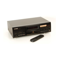
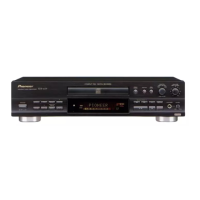
Description of front panel controls and features.

Remote Control Unit

Explanation of remote control buttons and their functions.

Specifications

Technical specifications of the PDR-W739 unit.

Related product manuals