Do you have a question about the Pioneer PL-L1000 and is the answer not in the manual?
Details on drive system, motor, platter, speeds, and wow/flutter.
Specifications for build-up time, speed deviation, and speed stability.
Information on speed variation due to time and temperature changes.
Type, effective arm length, overhang, and weight of the tonearm assembly.
Lists automatic functions like auto lead-in, auto-return, and quick play.
List of ICs, transistors, diodes, and Hall elements used.
Power requirements, dimensions, weight, and accessories included.
Description of the main power on/off switch functionality.
Explains the function of the quartz lock indicator light.
How to select between 33-1/3 and 45 RPM speeds.
How to set the turntable for different record sizes (12", 10", 7").
Functionality of the repeat play mode switch.
Controls the manual raising and lowering of the tonearm.
Initiates auto play and stops the operation.
Knob for manual remote control of tonearm movement.
Explanation of the tonearm's purpose and manual/remote operation.
Secures the tonearm during transport or storage.
Holds the tonearm pipe when not in use.
Discusses the platter's rotation and the mat's function.
Protective cover for the turntable and records.
Steps to remove the main panel and top cover.
Procedure for removing the direct-drive motor.
Instructions for disassembling and removing the tonearm.
Steps for removing the CdS detector and lamp components.
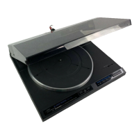
Visual identification of external parts and their part numbers.
Visual identification of internal components like motor and control assembly.
Details the operation of the tonearm control logic.
Describes the circuit for detecting the end of a record.
Explains the logic for raising and lowering the tonearm.
Logic for automatic switching based on record size.
Functionality of the repeat play mode control.
Circuitry for detecting record position and controlling descent.
Circuit for LED display and plunger operation.
Operation of the manual tonearm movement stage.
How the tracking sensor drives the tonearm.
Control logic for the direct-drive motor.
Detailed description of the full automatic operation logic.
Description of the circuit responsible for tonearm movement control.
Adjusting the motor's operating point for stable rotation.
Setting the correct timing for the tonearm's auto lead-in.
Adjusting the sensitivity of the end-of-record sensor.
Calibrating the timer for end-of-record detection.
Setting the zero point for the tracking sensor.
Adjusting the gain of the tracking sensor.
Setting the correct speeds for lead-in and return operations.
Timing sequence for the lead-in and playback operation.
Timing sequence for the reject (return) operation.
Timing sequence for the repeat playback function.
Guides for diagnosing issues within the device's electronic circuits.
Guides for diagnosing issues related to the turntable's mechanical components.
Visual breakdown of the turntable's external components.
Visual breakdown of the tonearm assembly.
Visual breakdown of the EV mechanism components.
Visual breakdown of the turntable's bottom plate and associated parts.
List of items included in the packing for shipment.
List of included accessories such as tools and adapters.
List of semiconductor components used on the PCB.
List of resistors used on the PCB with their part numbers.
List of capacitors used on the PCB with their part numbers.
List of semiconductor components used on the PCB for S/G model.
List of resistors used on the PCB for S/G model.
List of capacitors used on the PCB for S/G model.
| Platter | Aluminum die-cast |
|---|---|
| Tonearm | Linear tracking |
| Speeds | 33 1/3, 45 RPM |
| Motor | DC servo motor |
| Wow and Flutter | less than 0.025% WRMS |
| Signal-to-Noise Ratio | 78 dB (DIN-B) |