Do you have a question about the Pioneer RG-9 and is the answer not in the manual?
Read, retain, heed, and follow all operating and safety instructions provided with the appliance.
Avoid water, ensure stable location, proper ventilation, and keep away from heat sources.
Use correct power sources, protect cords, and keep antennas away from power lines.
Prevent object/liquid entry, handle damage requiring service, and clean with care.
Expands music source dynamic range via upward and downward expansion for a powerful rendition.
Fast and slow response control signal preserves attack and release characteristics of audio.
Reduces underlying source noise like tape hiss and motor rumble for exciting stereo sound.
Sensor uses energy distribution filter to ensure expansion is not triggered by noise components.
Switchable in 3dB steps from 4dB to 16dB for optimum expansion based on music source.
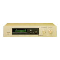
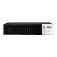
Slim design with a Fluoroscan display for a clean, fresh look.
Connect to TAPE REC jacks on stereo amplifier or PREAMP OUT jacks on preamplifier.
Connect to TAPE PLAY jacks on stereo amplifier or POWER AMP IN jacks on power amplifier.
Connect to INPUT (REC) jacks on the tape deck.
Connect to OUTPUT (PLAY) jacks on the tape deck.
Auxiliary unswitched power outlet for tape deck or other hi-fi components (max 100W).
Connect RG-9 PROCESSOR INPUT/OUTPUT to stereo amplifier's TAPE REC/PLAY jacks.
Connect tape deck's input/output jacks to RG-9 TAPE REC/PLAY jacks if amplifier has only one tape set.
Connect tape deck's recording input jacks to RG-9 TAPE REC jacks.
Connect tape deck's playback output jacks to RG-9 TAPE PLAY jacks.
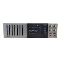
Includes the power switch and power indicator for basic operation and status.
Features meter, indicators, selector, and input level control for adjusting dynamic expansion.
Includes tape monitor switch and indicator for monitoring tape sound during operations.
Engages or bypasses the expansion effect for instant comparison between processed and unprocessed signals.
Set controls and switches to specified positions before operating the RG-9.
Steps for playing source, engaging processor, adjusting controls for desired effect.
Guidance on RG-9 effect on music source and recommended selector settings for different genres.
Explains how level differences between channels are expanded, affecting sound ambience.
How to use RG-9 tape monitor switch in place of the amplifier's when bypassing the processor.
Explains how the dynamic expansion meter indicates instantaneous maximum expansion amount.
Explains RG-9's function to expand level variations via gain control amplifier and sensor section.
Shows the circuit composition of flat frequency response gain control amplifier and sensor section.
Illustrates how output level varies with input level for different expansion settings.
Shows how gain changes in response to input level changes for various expansion settings.
Diagram and table showing connections and settings for using RG-9 with SG-9 graphic equalizer.
Diagram showing connections for using RG-9 with SR-9 reverberation amplifier.
Example combination of RG-9, SG-9, and SR-9 for optimal sound. Connect components properly.
Details maximum output voltage, total harmonic distortion, dynamic expansion gain, and impulse response.
Covers power requirements, power consumption, dimensions, and weight of the unit.
Lists the items provided with the unit, such as connection cords and operating instructions.
| Brand | Pioneer |
|---|---|
| Model | RG-9 |
| Category | Recording Equipment |
| Language | English |