Do you have a question about the Pioneer RT-909 and is the answer not in the manual?
Describes the signal path during tape playback.
Describes the signal path during tape recording.
Explains the operation of the bias oscillator circuit.
Details the circuit switching playback direction.
Explains how the FL meter display is driven.
Describes the logic and sequence of control operations.
Details the circuit controlling the reel motors.
Explains the operation of the tape counter circuit.
Adjusts tape take-up torque and back tension for stable transport.
Adjusts the tape transport speed for accuracy.
Adjusts playback head sensitivity and balance.
Adjusts recording head level and response.
Adjusts the unit's internal power supply voltages.
Sets playback signal output levels for both channels.
Calibrates playback equalization for frequency accuracy.
Detailed schematic of the unit's control logic circuits.
Circuit schematic for the control section of the D/G model.
| Wow and Flutter | 0.04% (19 cm/s) |
|---|---|
| Frequency Response | 20Hz to 28kHz (19 cm/s) |
| Total Harmonic Distortion | 0.8% |
| Weight | 21kg |
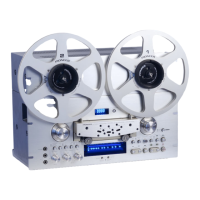
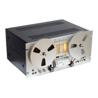
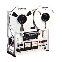
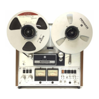
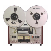
| Type | Reel to Reel |
| Track System | 4-track, 2-channel stereo |
| Tape Speed | 19 cm/s, 9.5 cm/s |
| Heads | 3 |
| Motors | 2 x reel, 1 x capstan |
| Reel Size | Up to 10.5 inch reel |