EasyManua.ls Logo

Pioneer S-DV77 User Manual

Pioneer S-DV77
34 pages
To Next Page IconTo Next Page
Page #1 background imageLoading...
Page #1 background image
ORDER NO.
PIONEER CORPORATION 4-1, Meguro 1-chome, Meguro-ku, Tokyo 153-8654, Japan
PIONEER ELECTRONICS SERVICE, INC. P.O. Box 1760, Long Beach, CA 90801-1760, U.S.A.
PIONEER EUROPE NV Haven 1087, Keetberglaan 1, 9120 Melsele, Belgium
PIONEER ELECTRONICS ASIACENTRE PTE. LTD. 253 Alexandra Road, #04-01, Singapore 159936
PIONEER CORPORATION 2001
c
RRV2473
T – ZZR JUNE 2001 Printed in Japan
SPEAKER SYSTEM
This product is component of system.
Component System Service Manual Remarks
SPEAKER SYSTEM S-DV77
POWERED SUBWOOFER S-DV77SW RRV2473
S-DV77ST RRV2473
S-DV77
Type
Model
Power Requirement Remarks
S-DV77
MYXJI AC220-230V
NVXJI AC230V
THIS MANUAL IS APPLICABLE TO THE FOLLOWING MODEL(S) AND TYPE(S).
SATELLITE SPEAKER
S-DV77SW
S-DV77ST
1. SAFETY INFORMATION
......................................
2
2. EXPLODED VIEWS AND PARTS LIST
...............
4
3. BLOCK DIAGRAM AND SCHEMATIC DIAGRAM
...
12
4. PCB CONNECTION DIAGRAM
.........................
22
5. PCB PARTS LIST
...............................................
30
6. ADJUSTMENT
....................................................
32
CONTENTS
7. GENERAL INFORMATION
................................
33
7.1 DISASSEMBLY
............................................
33
8. PANEL FACILITIES AND SPECIFICATIONS
.......
34
Question and Answer IconNeed help?

Do you have a question about the Pioneer S-DV77 and is the answer not in the manual?

Pioneer S-DV77 Specifications

General IconGeneral
BrandPioneer
ModelS-DV77
CategorySpeakers
LanguageEnglish

Summary

Safety Information and Notices

Safety Precautions for Service and Customers

Essential safety checks and warnings for service technicians and customers.

Product Safety Component Notice

Guidelines on special safety characteristics of components and replacement parts.

Exploded Views and Parts Lists

Packing Exploded View and Parts

Exploded view diagram detailing the product's packing components.

Powered Woofer Section Exploded View

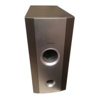
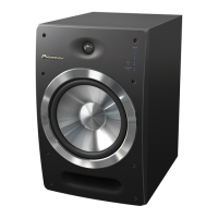
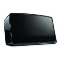
Exploded view and parts identification for the powered woofer unit.

Satellite Speaker Section Exploded Views

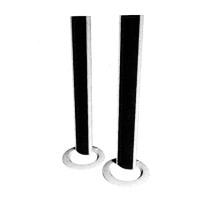
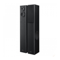
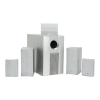
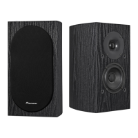
Exploded views and parts identification for satellite speaker assemblies.

Amplifier Assembly Exploded View

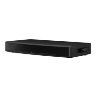
Exploded view and parts identification for the main amplifier assembly.

Block Diagrams and Schematic Diagrams

System Block Diagram and Connections

Overall system block diagram and electrical connection schematic.

AF Assembly Schematic (Part 1)

Schematic diagram detailing the Audio Frequency (AF) assembly, part 1.

AF (Part 2), REG, and TRADE Assembly Schematics

Schematics for AF assembly (part 2), REG, and TRADE assemblies.

Amplifier Assembly Schematic

Schematic diagram for the main Amplifier (AMP) assembly.

Primary Assembly Schematic

Schematic diagram for the Primary (PRI) power supply assembly.

PCB Connection Diagrams

AF Assembly PCB Connections

PCB layout and connection points for the AF assembly.

AMP Assembly PCB Connections

PCB layout and connection points for the AMP assembly.

PRI, REG, and TRADE Assembly PCB Connections

PCB layouts and connection points for PRI, REG, and TRADE assemblies.

PCB Parts List

Adjustment Procedures

General Information and Disassembly

Disassembly Procedures

Step-by-step guide for disassembling the product's main components.

Technical Specifications

Related product manuals