Do you have a question about the Pioneer SX-SW606 and is the answer not in the manual?
Identifies the product category and type.
Lists applicable models and types for the manual.
Outlines essential safety checks for customer and technician protection.
Details the procedure for measuring leakage current.
Highlights special safety characteristics of electrical and mechanical parts.
Emphasizes conforming to regulations and maintaining a safe servicing environment.
Focuses on performing optimum adjustments for product performance.
Advises on using specified substances and proper application amounts.
Details proper cleaning procedures for restoring performance.
Explains how to protect products from damage during transit.
Details specifications for the SX-SW404 and SX-SW606 models.
Details specifications for the SX-X360 model.
Lists the included accessories for the models.
Provides an exploded view and parts list for the packing section.
Compares parts across different models, highlighting differences.
Shows differences in exterior parts between models.
Lists parts for the SX-SW404/SX-SW606 display unit.
Lists parts for the SX-X360 display unit.
Shows the overall system wiring and block connections.
Details the DFL Assy for specific models.
Details the CONNECT Assy for specific models.
Describes the digital audio PWM processor section.
Details the power stage section of the amplifier.
Explains the power stage of the amplifier.
Details the AC inlet assembly for specific models.
Details the connector assembly for specific models.
Lists and describes the switches on the FL Assy.
Details the AC inlet assembly for the SX-X360 model.
Details the connector assembly for the SX-X360 model.
Lists and describes the switches on the FL Assy for SX-X360.
Shows waveforms for the main Assy.
Provides notes and explanations for PCB diagrams.
Illustrates the viewing perspective for PCB diagrams.
Shows PCB layout for the CONNECT ASSY (Side A).
Shows PCB layout for the CONNECT ASSY (Side B).
Shows PCB layout for the AC INLET ASSY.
Shows PCB layout for the CONNECT ASSY (Side A) for SX-X360.
Shows PCB layout for the CONNECT ASSY (Side B) for SX-X360.
Shows PCB layout for the AC INLET ASSY for SX-X360.
Shows PCB layout for the FL ASSY (Side A).
Shows PCB layout for the FL ASSY (Side B).
Shows PCB layout for the FL ASSY (Side A) for SX-X360.
Shows PCB layout for the FL ASSY (Side B) for SX-X360.
Shows the PCB layout for the power supply unit.
Lists PCB assemblies and their corresponding part numbers.
Highlights differences in PCB assemblies between models.
Lists contrasting parts for the Main Assy.
Lists contrasting parts for the AC Inlet Assy.
Lists PCB parts for specific models, noting exceptions.
Lists miscellaneous parts for the Main Assy.
Lists resistor part numbers with their values and codes.
Lists capacitor part numbers with their values and types.
Continues the list of resistors.
Continues the list of capacitors.
Lists capacitor part numbers with values and types.
Continues the list of capacitors.
Lists parts for the AC inlet assembly.
Lists miscellaneous components for the AC inlet.
Lists capacitors for the AC inlet assembly.
Lists parts for the AC inlet assembly for SX-X360.
Lists capacitors for the SX-X360 AC inlet assembly.
Lists parts for the CONNECT ASSY.
Lists miscellaneous components for the CONNECT ASSY.
Lists parts for the CONNECT ASSY for SX-X360.
Lists resistor part numbers with values.
Lists capacitor part numbers with values.
Notes that the power supply unit has no service parts.
Notes that the tuner unit has no service parts.
Details how to enter, quit, and indications in Test Mode.
Explains operations within Test Mode and function changes.
Lists possible failures related to EEPROM and communication lines.
Indicates a potential EEPROM failure.
Describes symptoms and causes of OC ERROR, including speaker terminal issues.
Explains OVERTEMP conditions and causes, including IC failures.
Describes how DSP errors are displayed and switched.
Explains how to check accumulated power-on time and speaker settings.
Explains speaker setup and sound-quality parameters.
Guides on selecting speaker settings via controls.
Explains how to confirm the current speaker setting.
Describes error indications when no speaker setting is present.
Details the format and meaning of DSP error displays.
Explains how to access DSP error messages using the SOUND key.
Describes the function of the PWM processor section.
Explains the power stage, including MOSFET control and protection.
Describes the output low-pass filter section.
Provides crucial warnings about short-circuiting speaker terminals.
Explains how protection circuits operate and notify the user.
Details the SHUTDOWN and XOTW ports for detection.
Specifies the timing for detection events.
Outlines conditions and FL display indications for protection circuits.
Explains the unit's shutdown process after protection activation.
Specifies conditions for switching the fan speed to high.
Specifies conditions for switching the fan speed to low.
Shows the fan drive circuit and voltage references for speed control.
Details compatibility between different receiver series.
Provides notes on SX-X360 compatibility and specific issues.
Lists reference models for SX-SW77 and SX-SW404 series.
Provides disassembly steps for the AXX7204 display unit.
Provides disassembly steps for the AXX7212 display unit.
Details how to remove the speaker.
Shows the bottom view of the Main Section.
Shows the rear view of the Main Section and its connections.
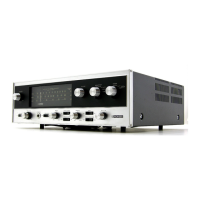
Describes the front panel controls and indicators of the display unit.
Illustrates and describes the rear panel connections and controls.
Provides pin arrangement and block diagram for the AK5358ET IC.
Shows the top-view pin layout of the AK5358ET IC.
Illustrates the block diagram of the AK5358ET IC.
Details the function of each pin for the AK5358ET IC.
Identifies the LC72725M IC as an RDS Decoder.
Shows the top-view pin arrangement of the LC72725M IC.
Illustrates the block diagram of the LC72725M IC.
Details the function of each pin for the LC72725M IC.
Identifies the IC as an 8-channel digital audio PWM processor.
Shows the top-view pin arrangement of the TAS5508BPAG IC.
Illustrates the block diagram of the TAS5508BPAG IC.
Details the function of each pin for the TAS5508BPAG IC.
Explains the meaning of I/O types used in pin functions.
Identifies the ICs as stereo digital amplifier power stages.
Shows the top-view pin arrangement of the TAS5142DDV ICs.
Illustrates the block diagram of the TAS5142DDV ICs.
Details the function of each pin for the TAS5142DDV ICs.
Identifies the IC as a system control microcomputer.
Shows the top-view pin arrangement of the PDC135A IC.
Details the function of each pin for the PDC135A IC.
Continues the pin function details for the PDC135A IC.
Explains port selection options for P00-P07.
Explains port selection options for P10-P17.
Explains port selection options for P20-P27.
Explains port selection options for P30-P36.
Explains port selection options for P70-P73.
Explains port selection options for P80-P87.
Explains port selection options for PA0-PA5.
Explains port selection options for PB0-PB7.
Explains port selection options for PCO-PC7.
Explains port selection options for PortE and PortF.
Advises on assigning RDSDATA and RDSCLK ports.
Identifies the IC as a low-power digital audio receiver.
Shows the top-view pin arrangement of the AK4117VF IC.
Illustrates the block diagram of the AK4117VF IC.
Identifies the IC as a 64x16 bit EEPROM.
Shows the top-view pin arrangement of the EEPROM.
Illustrates the block diagram of the EEPROM.
Details the function of each pin for the EEPROM.
Identifies the IC as a DSP IC.
Shows the top-view pin arrangement of the DSPIC.
Details the function of each pin for the DSPIC.
Continues the pin function details for the DSPIC.
Identifies the IC as an FL driver.
Shows the pin arrangement of the PT6315 IC.
Illustrates the block diagram of the PT6315 IC.
Details the function of each pin for the PT6315 IC.
Identifies the display module and its components.
Shows the pin assignment for the display unit.
Details the grid assignment for the display segments.
Illustrates the pin connections for the display.
Shows the anode connections for the display segments.
Describes the front panel controls and indicators of the display unit.
Lists applicable models for the display unit.
Illustrates and describes the rear panel connections and controls.
Highlights important notes regarding remote control functions.
Describes the RECORDER function.
Describes the RECEIVER function.
Explains the input selection buttons.
Describes the SOUND RETRIEVER function.
Details playback controls like PAUSE, PLAY, and STOP.
Explains REC and STOP REC functions.
Describes the INFO button function.
Explains the HELP button function.
Details functions for navigating discs and menus.
Explains the GUIDE Plus+ function.
Describes the HOME MENU function.
Explains cursor and ENTER button functions.
Describes the channel selection function.
Explains the CM BACK function.
Explains the CM SKIP function.
Explains the PAUSE LIVE TV function.
Explains the RETURN button function.
Describes PREV/NEXT button functions for navigation.
Explains the VOLUME adjustment.
Details action buttons for GUIDE Plus+ and DVD playback.
Explains audio language/channel selection.
Explains subtitle display/change.
Explains camera angle switching.
Explains play mode selection.
Explains timer recording setup.
Describes reverse/forward scanning and playback speed control.
Explains recording mode selection.
Explains the One Touch Copy function.
Details the use of number buttons for navigation and input.
Explains access to the surround sound setup menu.
Explains SR+ feature selection.
Explains how to start Auto MCACC setup.
Explains the use of test tone for speaker setup.
Explains Surround mode selection.
Explains sleep timer setting.
Explains selection of Advanced Surround mode.
Explains access to the sound menu.
Explains clearing entries.
Explains displaying the disc menu.
Explains changing DVD recorder input.
Explains switching between TV and DVD modes.
Explains JUKEBOX function.
Explains TV control functions.
Explains displaying on-screen information.
Explains changing RDS displays.
Explains switching between MAIN and SUB functions.
Details cleaning procedures before shipping.
| Brand | Pioneer |
|---|---|
| Model | SX-SW606 |
| Category | Stereo System |
| Language | English |