EasyManua.ls Logo

Pioneer TS7 User Manual

Pioneer TS7
74 pages
To Next Page IconTo Next Page
Page #1 background imageLoading...
Page #1 background image
ORDER NO.
PIONEER CORPORATION 4-1, Meguro 1-chome, Meguro-ku, Tokyo 153-8654, Japan
PIONEER ELECTRONICS (USA) INC. P.O. Box 1760, Long Beach, CA 90801-1760, U.S.A.
PIONEER EUROPE NV Haven 1087, Keetberglaan 1, 9120 Melsele, Belgium
PIONEER ELECTRONICS ASIACENTRE PTE. LTD. 253 Alexandra Road, #04-01, Singapore 159936
PIONEER CORPORATION 2002
ARP3129
CANAL PLUS TUNER
TS7
T – ZZV AUG. 2002 Printed in Japan
TS7
OK
CB
/ I
BCT-1710
BCT-1720
BCT-1730
Type
Model
Power Requirement Remarks
TS7
BCT-1710 BCT-1720 BCT-1730
NYXK/FR –––AC230V
NYXK/SP ––AC230V
NYXK/IT –– AC230V
NYWXK/PL ––– AC230V
THIS MANUAL IS APPLICABLE TO THE FOLLOWING MODEL(S) AND TYPE(S).
For details, refer to "Important symbols for good services" on the next page.
w
w
w
.
x
i
a
o
y
u
1
6
3
.
c
o
m
Q
Q
3
7
6
3
1
5
1
5
0
9
9
2
8
9
4
2
9
8
T
E
L
1
3
9
4
2
2
9
6
5
1
3
9
9
2
8
9
4
2
9
8
0
5
1
5
1
3
6
7
3
Q
Q
TEL 13942296513 QQ 376315150 892498299
http://www.xiaoyu163.com
Question and Answer IconNeed help?

Do you have a question about the Pioneer TS7 and is the answer not in the manual?

Pioneer TS7 Specifications

General IconGeneral
BrandPioneer
ModelTS7
CategoryTuner
LanguageEnglish

Summary

SAFETY INFORMATION

SAFETY PRECAUTIONS

General safety precautions for customer and service technician protection.

PRODUCT SAFETY NOTICE

Notice about special safety characteristics of electrical and mechanical parts.

SPECIFICATIONS

EXPLODED VIEWS AND PARTS LIST

PACKING

Details of product packing and contents.

EXTERIOR

Exploded view illustrating the exterior parts of the unit.

BLOCKDIAGRAM AND SCHEMATIC DIAGRAM

BLOCKDIAGRAM

Overall block diagram illustrating the system's functional units and connections.

MAIN ASSY SCHEMATICS

Detailed schematics for the main assembly, broken into parts (1/8 to 8/8).

PCB CONNECTION DIAGRAM

FRONT ASSY PCB Layout

PCB connection diagram for the front assembly, showing component placement.

CARD and MODEM ASSYS PCB Layout

PCB connection diagrams for Card and Modem assemblies.

MAIN ASSY PCB Layout

PCB layout diagram for the main assembly, showing component positions.

PCB PARTS LIST

MAIN ASSY PARTS

List of major PCB assemblies and their corresponding part numbers.

ADJUSTMENT

GENERAL INFORMATION

DIAGNOSIS

Diagnostic procedures for troubleshooting the IRD unit.

TROUBLESHOOTING

Detailed steps for identifying and resolving common IRD faults.

TS7 REPAIRS

POWER SUPPLY ASSY CHECK

Procedure to check the power supply assembly for faults.

IIC_BUS CHECK

Procedure to check the IIC bus communication.

ANALOG SIGNAL CHECKS

Checks for Analog Video, Audio, and Tuner reception functionality.

IC INFORMATION

STV0299B QPSK Link IC

Details and block diagram for the STV0299B QPSK Link IC.

CS4334-KS DAC IC

Details and block diagram for the CS4334-KS DAC IC.

HIN211CA RS232C IC

Details and block diagram for the HIN211CA RS232C IC.

IC LOCATIONS

MAIN ASSY IC Layout

Layout of ICs on the main assembly board, identified by component type.

PANEL FACILITIES

FRONT PANEL Description

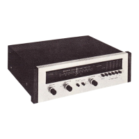
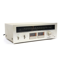
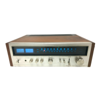
Description and illustration of the front panel controls and indicators.

REAR PANEL Description

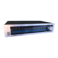
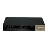
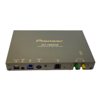
Description and illustration of the rear panel connectors and terminals.

Related product manuals