Do you have a question about the Pioneer VSX-916-S and is the answer not in the manual?
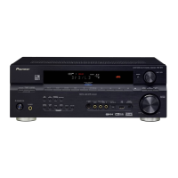
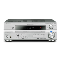
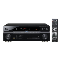
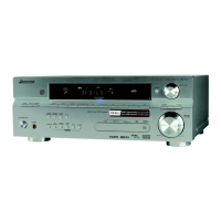
Lists applicable models (VSX-816-K/S, VSX-916-K/S) and their power requirements.
General safety precautions and leakage current check for customer protection.
Highlights special safety characteristics of electrical and mechanical parts.
Conforming to product regulations and maintaining a safe servicing environment.
Procedures for maintaining original performance and confirming characteristics.
Use of specified substances and proper application amounts.
Details continuous power output, input sensitivity, frequency response, tone control, and signal-to-noise ratios.
Input/output sensitivity, frequency response, and crosstalk for video signals.
Frequency range, sensitivity, quieting, signal-to-noise, distortion, selectivity, and separation.
Exploded view of packing components and part numbers.
Compares parts across different models (VSX-816/916 series).
Lists part numbers for external components identified by marks in the diagram.
Lists part numbers for front panel components.
High-level functional overview of the receiver's internal sections and signal flow.
Diagram showing how major internal assemblies are interconnected via cables and connectors.
Schematic diagram for the main assembly, part 1 of 3.
Schematic diagram for the headphone assembly.
Schematic diagram for the pre-out assembly.
Schematic diagram for the 5.1 channel input assembly.
Schematic diagram for the front display assembly.
Schematic diagram for the rotary encoder assembly.
Schematic diagram for the power key assembly.
Schematic diagram for the S-Video assembly.
Schematic diagram for the Trans 4 assembly.
Schematic diagram for the regulator assembly.
Schematic diagram for the video assembly.
Schematic diagram for the digital input assembly.
Schematic diagram for the front video assembly.
Schematic diagram for the primary assembly.
Schematic diagram for the Trans 1 assembly.
PCB layout for the USB IN assembly.
PCB layout for the main assembly.
PCB layout for the DSP assembly, specific to VSX-916.
Lists major assemblies and their corresponding part numbers.
Compares PCB assemblies across different models.
Lists various capacitor types, their part numbers, and locations.
Lists miscellaneous components like ICs, diodes, transistors, and connectors.
Lists various capacitor types, their part numbers, and locations.
Lists various capacitor types, their part numbers, and locations.
Lists various capacitor types, their part numbers, and locations.
Lists ICs, diodes, transistors, connectors, and other components.
Lists various capacitor types, their part numbers, and locations.
Lists ICs, diodes, transistors, connectors, and other components.
Lists various capacitor types, their part numbers, and locations.
Lists various capacitor types, their part numbers, and locations.
Lists ICs, diodes, transistors, connectors, and other components.
Lists various capacitor types, their part numbers, and locations.
Lists various capacitor types, their part numbers, and locations.
Lists ICs, diodes, transistors, connectors, and other components.
Lists various capacitor types, their part numbers, and locations.
Lists various capacitor types, their part numbers, and locations.
Lists various capacitor types, their part numbers, and locations.
Lists ICs, diodes, transistors, connectors, and other components.
Lists various capacitor types, their part numbers, and locations.
Lists various capacitor types, their part numbers, and locations.
Lists various capacitor types, their part numbers, and locations.
Lists ICs, diodes, transistors, connectors, and other components.
Lists various capacitor types, their part numbers, and locations.
Lists ICs, diodes, transistors, connectors, and other components.
Lists ICs, diodes, transistors, connectors, and other components.
Lists ICs, diodes, transistors, connectors, and other components.
Lists various capacitor types, their part numbers, and locations.
Notes on the FM/AM tuner unit, indicating it has no service part.
Information on diagnosing issues with the unit.
Step-by-step instructions for disassembling the unit.
Visual guide illustrating key steps in diagnosing internal assemblies and connections.
List of integrated circuits (ICs) used in the unit with their part numbers and locations.
Detailed mapping of pin numbers to their functions for the main MCU.
Physical pin layout of the NJM2243M IC.
Functional block diagram of the NJM2243M IC.
Physical pin layout of the NJM2595M IC.
Functional block diagram of the NJM2595M IC.
Description of the IC's main functions, including volume and input selection.
Functional block diagram of the R2S15205FP IC.
Explains the DC detection circuit, overload detection, and fan stop protection.
Details the operation of protection circuits for DC abnormality, overload, and fan stop.
Flowchart explaining fan stop detection and its relation to DC abnormality.
Block diagram illustrating the USB module's components and connections.
Explains error codes displayed on the FL display related to USB operations.
Step-by-step troubleshooting guide for USB connectivity and power issues.
Diagram and labels for the front panel controls and indicators.
Function of the RECEIVER button for switching between receiver and other components.
Buttons used to control other connected components.
Buttons for direct selection, player controls, and basic receiver functions.
Buttons for tuner operation, component selection, and system setup access.
Dedicated buttons for controlling a connected TV.
Buttons for controlling components after selecting them via MULTI CONTROL.
Buttons for selecting listening modes, surround settings, and playback options.
Accesses DVR controls and other receiver functions.
Lists service parts, such as SR+ mini-plug cables.
Explains how to connect and use the SR+ mode with a Pioneer plasma display for enhanced features.
Lists positions on the product that require cleaning before shipping.