Do you have a question about the Pioneer X-HM10-S and is the answer not in the manual?
Guidelines for using lead-free solder and appropriate soldering iron temperatures for environmental protection.
Procedure for removing solder on a short circuit point after connecting a flexible cable.
Diagrams showing the location of various PCBs within the unit for service purposes.
List of lubricants and glues required for service procedures, referencing the disassembly section.
A comprehensive diagram illustrating the wiring connections between different PCB assemblies.
Flowcharts and checks for diagnosing power issues and 'NO DISC' display errors.
Procedure for removing the top cabinet, including screw locations and handling notes.
Steps to remove the iPod PCB assembly, involving cable disconnection and screw removal.
Instructions for disassembling the front panel, including cable and connector removal.
Steps for removing the Radio PCB assembly after top cabinet and screw removal.
Procedure for removing the Power PCB assembly, detailing screw and connector disconnection.
Steps for removing main PCB, loader assembly, and CD mecha unit.
Instructions for updating the unit's firmware via a USB device.
Exploded view and parts list for the packing configuration of the unit.
Exploded view and parts list detailing the exterior components of the unit.
Schematic for the main PCB, part 1 of 7, covering power and input/output interfaces.
Schematic for the main PCB, part 2 of 7, detailing memory and interface connections.
Schematic for the main PCB, part 3 of 7, showing power supply and control circuits.
Schematic for the main PCB, part 4 of 7, focusing on USB and iPod interface circuits.
Schematic for the main PCB, part 5 of 7, illustrating the Class-D amplifier and headphone circuits.
Schematic for the main PCB, part 6 of 7, covering audio interfaces and clock generation.
Schematic for the main PCB, part 7 of 7, detailing the CD section and motor control.
Schematic for the iPod PCB assembly, showing docking and interface connections.
Schematic diagram for the Radio PCB, including tuner and antenna connections.
Schematic diagram for the Display PCB, showing connections to the LCD and control signals.
Schematic diagram for the Key-Switch PCB, illustrating button and resistor connections.
Schematic diagram for the Headphone PCB, showing audio output and switch connections.
Schematic diagram for the Power PCB, detailing power supply circuits and voltage regulation.
Schematic diagram for the USB PCB, showing connector and interface circuitry.
Diagram showing PCB connections between the Main PCB and iPod PCB assemblies.
Diagram showing PCB connections between Display and Key-Switch PCB assemblies.
Diagram showing PCB connections for the Radio PCB assembly.
Diagrams showing PCB connections for Headphone and USB PCB assemblies.
Diagram showing PCB connections for the Power PCB assembly.
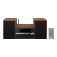
| Brand | Pioneer |
|---|---|
| Model | X-HM10-S |
| Category | Car Receiver |
| Language | English |