Do you have a question about the Pioneer X-HM20-K and is the answer not in the manual?
Service manual is for qualified technicians; improper repairs affect safety.
Product may contain chemicals known to cause cancer or birth defects.
Apparatus contains Class 1 Laser; servicing by instructed persons only.
Identifies Class 1 Laser Product classification and caution labels on the unit.
Guidance on using lead-free solder, soldering iron temperature, and solder types.
Procedure for removing solder on short circuit point before replacing CD mecha unit.
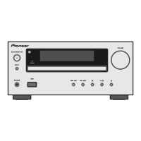
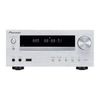
Details power source, consumption, dimensions, and weight of the unit.
Specs for amplifier output, CD player type, D/A converter, and response.
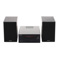
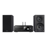
Specs for speakers (X-HM20/10) and USB host interface/file support.
Diagrams showing the location of various PCBs within the unit.
Lists necessary jigs for service procedures.
Illustrates the complete wiring connections between major components.
Block diagram showing connections for the radio PCB.
Block diagram showing connections for the headphone PCB.
Block diagram showing connections for the USB PCB.
Block diagram showing connections for the main PCB.
Block diagram showing connections for the iPod PCB.
Block diagram showing connections for the display PCB.
Block diagram showing connections for the key-switch PCB.
Block diagram showing connections for the power PCB.
Step-by-step guide to diagnose and resolve 'No Power' issues.
Steps to diagnose and fix 'NO DISC' errors when a CD is inserted.
Instructions for removing the top cabinet of the unit.
Steps to remove the iPod PCB assembly from X-HM20 models.
Steps to remove the volume knob, nut, washers, and front panel section.
Instructions for removing display, key-switch, headphone, and USB PCB assemblies.
Method to open the CD tray when the power is off.
Procedure to update the unit's firmware via USB.
Steps to verify the currently installed software version.
Exploded view and parts list for the packing materials.
Details model-specific part differences in packing.
Details model-specific part differences in exterior components.
Schematic details for the first part of the main PCB.
Schematic details for the second part of the main PCB.
Schematic details for the third part of the main PCB.
Schematic details for the fourth part of the main PCB.
Schematic details for the fifth part of the main PCB.
Schematic details for the sixth part of the main PCB.
Schematic details for the seventh part of the main PCB.
Schematic for the iPod PCB assembly.
Schematic for the Radio PCB assembly.
Schematic for the Display PCB assembly.
Schematic for the Key-Switch PCB assembly.
Schematic for the Headphone PCB assembly.
Schematic for the Power PCB assembly.
Schematic for the USB PCB assembly.
Schematic for the iPod 30pin docking socket.
Diagrams showing physical connections between Main and iPod PCBs.
Diagrams showing connections for Display and Key-Switch PCBs.
Diagrams showing connections for the Radio PCB assembly.
Diagrams showing connections for Headphone and USB PCBs.
Diagrams showing connections for the Power PCB assembly.
Diagrams showing connections for the Radio PCB assembly (Side B).
Diagrams showing connections for Headphone and USB PCBs (Side B).
Diagrams showing connections for the USB PCB assembly.
Diagrams showing connections for the Power PCB assembly.
| Brand | Pioneer |
|---|---|
| Model | X-HM20-K |
| Category | Car Receiver |
| Language | English |