Do you have a question about the Pioneer XC-P410T and is the answer not in the manual?
General safety precautions for handling the appliance and potential hazards.
Procedure to check for leakage current using an AC leakage tester.
Important electrical and mechanical safety information for service technicians.
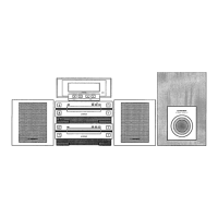
Exploded view and parts list for the exterior components of the unit.
Exploded view and parts list for the front panel section.
Exploded view and parts list for the multi-mechanism assembly.
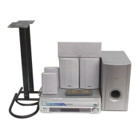
List of packing materials and related parts for the unit.
Connection diagram for PC boards specific to the XC-P410M model.
Connection diagram for PC boards specific to the XC-P410T model.
Detailed parts list for PC boards related to the XC-P410M model.
Detailed parts list for PC boards related to the XC-P410T model.
Procedure for disassembling the CD section of the XC-P410M model.
Procedures and tools for adjusting the CD section of the unit.
Detailed steps for various adjustments including focus, grating, tracking, and RF levels.
List of required measuring instruments and tools for CD section adjustments.
Procedures for tuning and adjusting the FM and AM tuner sections of the unit.
Details on the PDB026C (IC601) microcomputer, including pin functions and active states.
Pin configurations and timing charts for BU2040 (IC602) and IC211.
Block diagram and function details for the TC9237N (IC501) DA converter.
Details serial interface connections and timing for Tuner and CD section CPUs.
Block diagram showing audio signal flow for the XC-P410M model (L channel).
Block diagram showing audio signal flow for the XC-P410T model (L channel).
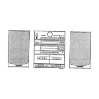
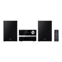
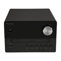
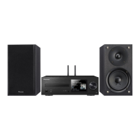
Identification of controls and indicators on the Amplifier and Tuner panels for XC-P410M.
Explanation of the Demo mode function for setting and canceling.
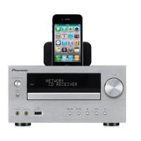
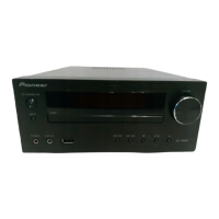
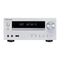
Identification of controls and indicators on the Amplifier and Tuner panels for XC-P410T.
Technical specifications for the XC-P410M amplifier section (U.S. and Canadian models).
Technical specifications for the FM, AM, and LW tuner sections.
Technical specifications for the CD section, power, dimensions, and operating temperature.
List of accessories and important notes regarding specifications.
| Brand | Pioneer |
|---|---|
| Model | XC-P410T |
| Category | Car Receiver |
| Language | English |