Do you have a question about the Pioneer XR-P170C and is the answer not in the manual?
Details precautions for handling the laser diode and interlock mechanism.
Schematic showing overall system connections and the trans assy.
Schematic diagram for the FM/AM tuner module.
Schematics for motor, switch, and CD assemblies.
Schematic diagrams for the deck and shield assemblies.
Schematic diagram for the AF (Audio Frequency) assembly.
Schematic diagram for the power supply assembly.
Schematics for CD SW, LED, display, LCD, and lamp assemblies.
Procedures for adjusting the FM and AM tuner sections.
Procedures for adjusting cassette deck mechanical and electrical functions.
Procedure for adjusting the Vp voltage in the power supply section.
Instructions for entering, operating, and exiting test modes.
Guides for diagnosing and resolving common system malfunctions and error codes.
| Tuner | AM/FM |
|---|---|
| CD Player | Yes |
| Bluetooth | No |
| Functions | CD, Radio, Cassette |
| Cassette Deck | Yes |
| Remote Control | Yes |
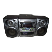
| Type | Mini Stereo System |
| Speakers | 2-way bass reflex |
| Amplifier | Built-in |