Do you have a question about the Pioneer XR-A100 Series and is the answer not in the manual?
| Brand | Pioneer |
|---|---|
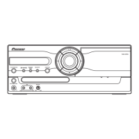
| Model | XR-A100 Series |
| Category | Stereo System |
| Language | English |
Product label checks and warnings, focusing on laser safety compliance.
Details on laser interlock mechanism and risks of exposure to laser beams.
Comparison of part numbers and differences across various receiver models.
Comparison of PCB assemblies, highlighting variations across different model types.
Details and contrast table for the MF Display Assembly.
Details and contrast table for the OF LCD Assembly.
Details and contrast table for the NF Lamp Assembly.
Detailed parts list for the FM/AM Tuner Module, including semiconductors, coils, and capacitors.
Detailed parts list for the AF Assy, covering semiconductors and components.
Parts list for the AF Trans Assy, detailing components and contrasting models.
Parts list for the KF AF Assy, detailing components and contrasting models.
Parts list for the CF Power Assy, including contrast tables and component details.
Schematic diagram for the FM/AM Tuner Module, detailing circuit connections.
Schematic diagram for the CF Power Assy, detailing circuit connections for various models.
Schematic diagram for the AF Trans Assy (YPWXJ model).
Schematic diagram for the AF Trans Assy (MYXK, NVXK models).
Schematic diagram for the KF AF Assy, detailing circuit connections for MYXK, NVXK, YPWXJ.
Schematic diagram for the MF Display Assy, showing connections.
Schematic diagram for the NF Lamp Assy, showing connections.
Schematic diagram for the OF LCD Assy, showing connections.
Schematic diagram for the F Deck Assy, illustrating circuit connections.
PCB connection diagram for TRANS and POWER assemblies, showing pinouts.
PCB layout for the EF FM/AM Tuner Module, showing component placement.
PCB layout for the F Deck Assy, showing component placement.
PCB layout for the KF AF Assy, showing component placement.
PCB layout for the OF LCD Assy, showing component placement.
PCB layout for the MF Display Assy, showing component placement.
PCB layout for the NF Lamp Assy, showing component placement.
Adjustment procedures for FM/AM Tuner Module, including sensitivity and distortion.
Adjustment procedures for AM Tuner Section, focusing on front-end sensitivity.
Procedure for adjusting Vp voltage in Power Assy using VR1001.