EasyManua.ls Logo

Pioneer XV-EV61 Service Manual

Pioneer XV-EV61
164 pages
To Next Page IconTo Next Page
Page #1 background imageLoading...
Page #1 background image
ORDER NO.
PIONEER CORPORATION 4-1, Meguro 1-chome, Meguro-ku, Tokyo 153-8654, Japan
PIONEER ELECTRONICS (USA) INC. P.O. Box 1760, Long Beach, CA 90801-1760, U.S.A.
PIONEER EUROPE NV Haven 1087, Keetberglaan 1, 9120 Melsele, Belgium
PIONEER ELECTRONICS ASIACENTRE PTE. LTD. 253 Alexandra Road, #04-01, Singapore 159936
PIONEER CORPORATION 2003
PGM
ADV.SURR. SFC
96kHz
LINE
REC
RDM RPT
1
MONO
RDS TUNED
STEREO
SUB Wf
NR
B.CUT REC ASES
RECWAKE
UPKARAOKE L RECHO KEY
PRO LOGIC DIGITAL
XV-EV61
RRV2793
STEREO DVD TUNER DECK RECEIVER
XV-EV61
XV-EV31
THIS MANUAL IS APPLICABLE TO THE FOLLOWING MODEL(S) AND TYPE(S).
This product is component of system.
Model Type Power Requirement
Regionalrestriction
codes (Region No.)
The voltage can be converted
by the following method.
XV-EV61 DLXJ/NC
110-127V/220-230V/240V
3 With the voltage selector
XV-EV31 DLXJ/NC
110-127V/220-230V/240V
3 With the voltage selector
Component System System Service manual
MINI SYSTEM X-EV61D X-EV31D
Stereo DVD Tuner Deck Receiver XV-EV61 XV-EV31 RRV2793(This manual)
Speaker System S-EV61V S-EV31V RRV2776(EV61), RRV2800(EV31)
T-ZZR JULY 2003 printed in Japan
For details, refer to "Important symbols for good services" .

Table of Contents

Other manuals for Pioneer XV-EV61

Question and Answer IconNeed help?

Do you have a question about the Pioneer XV-EV61 and is the answer not in the manual?

Pioneer XV-EV61 Specifications

General IconGeneral
BrandPioneer
ModelXV-EV61
CategoryStereo Receiver
LanguageEnglish

Summary

SAFETY INFORMATION

SPECIFICATIONS

EXPLODED VIEWS AND PARTS LIST

BLOCK DIAGRAM AND SCHEMATIC DIAGRAM

3.1 OVERALL BLOCK DIAGRAM

Overall system block diagram showing major component interconnections.

3.2 DVD SECTION BLOCK DIAGRAM

Block diagram of the DVD section, detailing signal paths and ICs.

3.3 OVERALL WIRING DIAGAM

Overall wiring diagram illustrating connections between major assemblies.

3.5 DVDM ASSY

Schematic diagram for the DVDM assembly (part 1 of 3).

3.6 DVDM ASSY

Schematic diagram for the DVDM assembly (part 2 of 3).

3.7 DVDM ASSY

Schematic diagram for the DVDM assembly (part 3 of 3).

3.8 DECK ASSY

Schematic diagram for the Deck Assy.

3.9 IF/AF ASSY

Schematic diagram for the IF/AF Assy (part 1 of 3).

3.10 IF/AF ASSY

Schematic diagram for the IF/AF Assy (part 2 of 3).

3.11 IF/AF ASSY

Schematic diagram for the IF/AF Assy (part 3 of 3).

3.12 DSP ASSY

Schematic diagram for the DSP Assy (part 1 of 2).

3.13 DSP ASSY

Schematic diagram for the DSP Assy (part 2 of 2).

3.14 DISP ASSY

Schematic diagrams for the Display (DISP) assemblies.

3.15 MIC ASSY

Schematic diagram for the Microphone (MIC) Assy.

3.16 EVOL ASSY

Schematic diagram for the EVOL Assy.

PCB CONNECTION DIAGRAM

PCB PARTS LIST

ADJUSTMENT

6.6 TEST MODE

Details on entering and using various test modes for diagnosis.

GENERAL INFORMATION

7.1.1 TEST MODE

Functional specification of the test modes for diagnosis.

Service Mode Functions

Details on service mode functions, error displays, and self-diagnosis.

ID Number and Data Setting

Procedure for setting player ID number and data, crucial for CPRM.

Troubleshooting Guide

Troubleshooting steps for microcomputer and DVD sections.

DSP Troubleshooting

Troubleshooting flowchart for DSP Assy issues specific to XV-EV61.

Protection Circuit Details

Explains protection circuits, their conditions, and specifications.

DISASSEMBLY Procedures

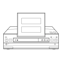
Step-by-step guide for disassembling the unit's front panel and main sections.

PARTS

PANEL FACILITIES

Remote Control Functions

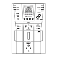
Identifies and describes the buttons on the remote control unit.

Related product manuals