Do you have a question about the Piper CHEROKEE WARRIOR 1976 and is the answer not in the manual?
This document is a Pilot's Operating Handbook for the Piper Warrior PA28-151, model year 1976, registration N7963F. It provides comprehensive information for the safe and efficient operation, maintenance, and flight planning of the aircraft.
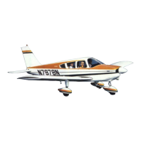
The Piper Cherokee Warrior PA-28-151 is a single-engine, fixed-gear monoplane constructed primarily of aluminum alloy, with low semi-tapered wings. It features four-place seating and a 200-pound baggage capacity. Fiberglass and thermoplastic materials are used in extremities like wing tips and engine cowlings, and in non-structural components. The fuselage is a semi-monocoque structure with a cabin door on the right side and a baggage door for loading into the 24 cubic foot compartment. The wing design incorporates a NACA 65-415 laminar flow airfoil section.
The aircraft is powered by a Lycoming O-320-E3D four-cylinder, direct-drive, horizontally opposed engine, rated at 150 HP at 2700 RPM. It is equipped with a starter, a 60 amp 14 volt alternator, shielded ignition, dual magnetos, a vacuum pump drive, a fuel pump, and a wetted polyurethane foam induction air filter. Engine cooling air is drawn from the nose section and routed through baffling, with an oil cooler located on the left rear of the engine. An optional winterization plate can be installed to restrict airflow during cold weather operation (below 50°F).
The propeller is either a McCauley 1C160/EGM7653 or a Sensenich 74DM6-0-58 fixed-pitch propeller, both made of aluminum alloy. The McCauley propeller has a diameter of 76 inches with a pitch of 53 inches, while the Sensenich has a 74-inch diameter with a 58-inch pitch. Both pitches are determined at 75% of the diameter.
The fuel system consists of two twenty-five gallon tanks (24 gallons usable each), totaling 50 U.S. gallons (48 gallons usable). The tanks are secured to the leading edge of each wing. A fuel tank selector control is located on the left side panel forward of the pilot's seat. An auxiliary electric fuel pump is provided for use in case of engine-driven pump failure, or during takeoffs, landings, and tank switching. Fuel drains are located at the bottom, inboard rear corner of each tank, and a fuel strainer with a quick drain is on the lower left front of the firewall.
Fuel Requirements: Minimum aviation grade fuel is 80/87 Red AVGAS ONLY. If 80/87 is unavailable, the lowest lead 100 grade (blue or green) may be used, but continuous use of higher leaded fuels (more than 25% of operating time) can increase engine deposits and require more frequent spark plug maintenance and oil changes.
The engine oil capacity is 8 quarts, with a minimum safe quantity of 6 quarts. Oil changes and filter replacements are recommended every 50 hours or sooner under unfavorable operating conditions. Recommended oil viscosity varies with ambient temperature: SAE 50 (above 60°F), SAE 40 (30°F to 90°F), SAE 30 (0°F to 70°F), and SAE 20 (below 10°F). Multi-viscosity options are also provided.
The aircraft features fixed landing gear with Cleveland 5.00 x 5 wheels on the nose gear and Cleveland 6.00 x 6 wheels on each main gear. All three tires are four-ply rating, type III with tubes. Main gear tires require a pressure of 24 psi, and the nose gear tire requires 30 psi. Cleveland single-disc hydraulic brake assemblies are on the main gear. The nose gear is steerable through a 30-degree arc each side of center via rudder pedals and toe brakes. A bungee assembly and shimmy dampener reduce steering effort and dampen shocks. The air-oil type struts have a normal static load extension of 3.25 inches for the nose gear and 4.50 inches for the main gear. The brake system uses MIL-H-5606 (petroleum base) hydraulic fluid, with a reservoir on the firewall. The parking brake is actuated by a hand lever.
The electrical system operates on 14 volts and includes a 60 amp alternator, a voltage regulator, an overvoltage relay, a battery contactor, and a standard 12 volt 25 ampere hour battery (or optional 35 ampere hour battery). The battery is located aft of the main spar on the right side of the fuselage. Electrical switches are on the right center instrument panel, and circuit breakers are on the lower right. The master switch is a split rocker switch ("BAT" and "ALT" sides). An ammeter indicates alternator load. An annunciator panel provides warnings for alternator, low oil pressure, and (if installed) low vacuum.
Dual flight controls are standard. The horizontal stabilator has a trim tab for pitch control, actuated by a trim control wheel on the console (forward for nose down, aft for nose up). The rudder is conventional with a trim mechanism (spring-loaded recentering device) on the right side of the pedestal (clockwise for nose right, counterclockwise for nose left). Manually controlled flaps extend to 10, 25, or 40 degrees via a handle between the front seats. The right flap has an over-center lock mechanism for use as a step when retracted. The throttle and mixture controls are on the control quadrant, with a friction adjustment lever. The carburetor heat control is placarded "ON" (down) and "OFF" (up).
The system provides pitot and static pressure for the airspeed indicator, altimeter, and optional vertical speed indicator. A pitot head on the bottom of the left wing collects pressure. An alternate static source is available via a valve below the instrument panel. Drain valves are provided for both pitot and static lines. An optional heated pitot head is available for icing conditions.
Cabin heat and defrost are supplied by a shroud attached to the muffler, regulated by controls on the instrument panel. Airflow between seats is regulated by heat diversion controls. Fresh air inlets are in the wing leading edges, with adjustable outlets at each front seat. Rear seat vents are optional. An optional overhead ventilating system with a blower (OFF, LOW, MED, HIGH) can be installed.
A 24 cubic foot baggage area is located behind the rear seat, accessible from the cabin or through a 20 x 22 inch outside baggage door on the right side of the fuselage. Maximum capacity is 200 pounds. Tie-down straps are available.
An audible alarm, located behind the instrument panel, indicates an approaching stall at five to ten knots above stall speed. Mild airframe buffeting may precede the stall. The stall warning system is inoperative with the master switch "OFF."
The handbook includes supplements for optional systems: